7
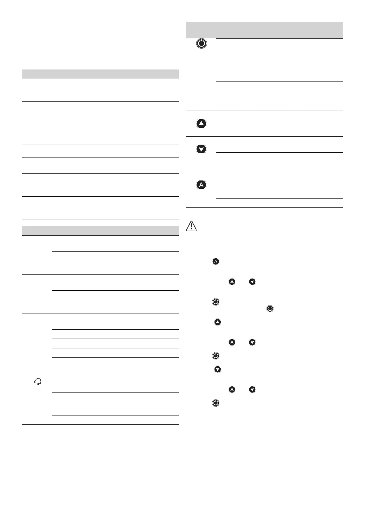
CONTROL PANEL (diagram C)
The meanings of the dierent control panel elements are
summarized on the following tables, where:
• O means lit LED light.
• ( ( O ) ) means slow-ashing.
• (((O))) means fast-ashing.
DISPLAY ACTION
OPERATION
MODE
Is showed on screen instantaneous
pressure or instantaneous current
consumption
ADJUSTMENT
MODE
Is displayed on screen the adjusted start
pressure blinking.
Is displayed on screen the adjusted stop
pressure blinking.
Is displayed the adjusted rated current
blinking (only SW2).
ALARM MODE Is displayed the alarm code
STAND-BY
MODE
Are displayed 3 ashing dots
BASIC CON-
FIGURATION
MODE
Is displayed the sequence of basic con-
guration parameters
ADVANCED
CONFIGURA-
TION MODE
Is displayed the sequence of advanced
conguration parameters
LEDS STATE MEANING
bar
O
It indicates the instantaneous pres-
sure in bar
( ( O ) )
It indicates the instantaneous pres-
sure in bar + pump operating (only
SW1)
psi
O
It indicates the instantaneous pres-
sure in psi
( ( O ) )
It indicates the instantaneous pres-
sure in psi + pump operating (only
SW1)
A
(only
SW2)
O
It indicates the instantaneous cu-
rrent consumption in Ampere units
( ( O ) ) Pump ON
START
O Is displayed the start pressure
( ( O ) ) Adjusting start pressure
STOP
O Is displayed the stop pressure
( ( O ) ) Adjusting stop pressure
O
Ratied dry-running or overload
alarms
( ( O ) )
Dry-running alarm performing ART
or overload alarm preforming any of
the 4 restore attempts
(((O))) Fast-cycling alarm
P-BUT-
TON
TOUCH ACTION
click!
From state ON: unit OFF.
From state OFF: the pump starts
and keeps operating until rea-
ching Pstop.
From any conguration MENU:
the parameter value is accepted.
HOLD
DOWN
From state ON: unit OFF.
From state OFF: the pump starts
and keeps operating until the
push-button is released.
click!
Pstart is displayed on the screen
for 3 seconds.
3” Pstart adjustment mode.
click!
Pstop is displayed on the screen
for 3 seconds.
3” Pstop adjustment mode.
click!
Is displayed on the screen instanta-
neous current consumption.
If it is already displayed then we
switch to instantaneous pressure
view.
3” Rated current adjustment.
STARTUP (diagram C)
Before starting the device please read the previous
sections, especially “Hydraulic Installation” and “Elec-
trical connection”.
Follow next steps:
1. Only for type SW2 set the pump rated current intensity
value.
- Press during 3 seconds.
- The current intensity value is displayed on screen, LED
A lights up and display is ashing.
- By mean of and is adjusted the rated current
reected in the characteristics plate of the motor. See
Note 1.
- Press for validation.
2. Start the device by pressing .
3. Set the cut-in (start) pressure:
- Press during 3 seconds.
- The start pressure value is displayed on screen, LED
START lights up and display is ashing.
- By mean of and is adjusted the start pressure
from 0,5 to 7 (*11) bar.
- Press for validation.
4. Set the cut-out (stop) pressure:
- Press during 3 seconds.
- The stop pressure value is displayed on screen, LED
STOP lights up and display is ashing.
- By mean of and is adjusted the stop pressure
from 1 to 8 (*12) bar.
- Press for validation.
5. The unit is ready to operate but more optional ad-
justments can be set through basic and advanced MENUS.
See the next chapter.
Remark 1: it is important to introduce exactly the ra-
ted current specied on the nameplate of the pump.
*+version
 Loading...
