fig. 8 - Rating label
2.4 Hydraulic connections
Never support the water
heater by the water/gas
connections. Make the
connections in
accordance with the
dimensions and connections
shown in section 4.1.
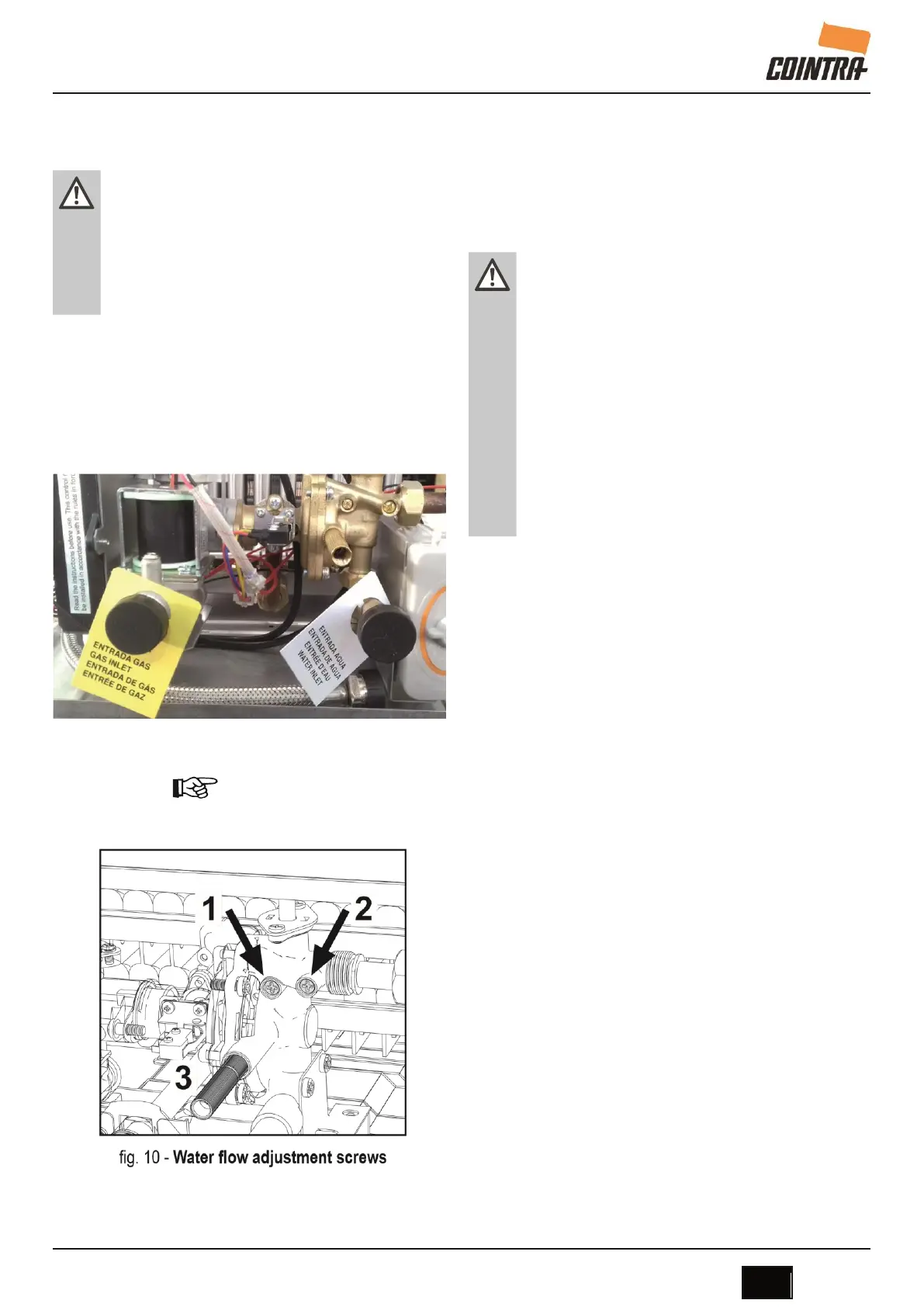
There are labels on the unit identifying the
1/2” water inlet pipe (white) and the 3/4” gas
inlet pipe (yellow).
fig. 9 - Connection cards
If the water hardness is over 25ºFr
(1ºF=10ppm CaCO3), the water must
be treated to avoid possible deposits on
the unit. 2.4.1 Water flow rate adjustment
Legend
1 - Minimum water flow
regulation screw.
2 - Maximum water flow
adjustment screw. 3 -
Safety valve drain water.
2.5 Gas connection
Before making the
connection, check that
the unit has been
prepared to operate with
the right type of fuel, and
carefully clean the gas
pipes to remove any
residue that might hinder
correct operation. Make
this connection in
accordance with the
dimensions and connections
in section 4.1.
1 Connect the corresponding gas inlet (see
section 4.2) in accordance with current
regulations in the country where the heater
is being installed.
2 Connect using a rigid metal pipe
(connection to a gas supply network) or
a flexible, continuous stainless steel
pipe (LPG installation), adding a shut-off
valve between the installation and the unit
(AS CLOSE TO THE UNIT AS POSSIBLE).
3 Once the connection to the gas network is
complete, check that all gas connections
are tight. For this purpose, a tightness test
must be performed. To avoid damage to
the unit due to excess pressure, leave the
gas inlet valve closed.
4 Check that the supplied pressure and gas
delivery values are those indicated for the
unit's consumption. See the technical data
table (section 4.5).
 Loading...