25
EN
CPA
Rev. 00 - 11/2018
6 938771 373372
PMS bar
tmax °C
D l/min
PMW bar
Qn (Hi)
Pn 80° - 60°
Pn 50° - 30°
kW
kW
kW
-
-
-
NOx
H
2 O
/
-
CPA 11
II2HM3+ (IT)
II2E+3+ (FR)
II2H3+ (ES - PT- GB)
3+ - G31/G30 - 37/29 mbar
21.1
18.9
8.1
6 (< 56 mg/kWh)
18
1840LX0001
- W IPX4D
Suitable for operation in a partially protected place
LEGGERE LE ISTRUZIONI TECNICHE PRIMA DELL’INSTALLAZIONE DELL’APPARECCHIO.
LEGGERE LE ISTRUZIONI D’USO PRIMA DELL’ACCENSIONE DELL’APPARECCHIO.
L’APPARECCHIO DEVE ESSERE INSTALLATO SOLO IN UN AMBIENTE CHE SODDISFI I NECESSARI REQUISITI
DI VENTILAZIONE O ALL’ESTERNO IN UN LUOGO PARZIALMENTE PROTETTO.
I3+ (BE)
10
3+ - G31/G30 - 37/29 mbar
LEGGERE LE ISTRUZIONI TECNICHE PRIMA DELL’INSTALLAZIONE
DELL’APPARECCHIO.
LEGGERE LE ISTRUZIONI D’USO PRIMA DELL’ACCENSIONE DELL’APPARECCHIO.
L’APPARECCHIO DEVE ESSERE INSTALLATO SOLO IN UN AMBIENTE CHE
SODDISFI I NECESSARI REQUISITI DI VENTILAZIONE O ALL’ESTERNO IN UN LUOGO
PARZIALMENTE PROTETTO.
READ THE TECHNICAL INSTRUCTIONS BEFORE INSTALLING THE
BOILER.
READ THE USER INSTRUCTIONS BEFORE OPERATING THE BOILER.
THE BOILER MUST BE INSTALLED IN A ROOM THAT MEETS THE
VENTILATION REQUIREMENTS OR OUTSIDE IN A PARTIALLY
PROTECTED PLACE.
0085
7.0
11.0
min
max
3+ - G31/G30 - 37/29 mbar
PMS bar
tmax °C
D l/min
PMW bar
Qn (Hi)
Pn 80° - 60°
Pn 50° - 30°
kW
kW
kW
-
-
-
NOx
H
2 O
2HM-2E-2H-2HS G20 20 mbar
26.8
23.8
10.7
6 (< 56 mg/kWh)
18
1840LX0003
Suitable for operation in a partially protected place
LEGGERE LE ISTRUZIONI TECNICHE PRIMA DELL’INSTALLAZIONE DELL’APPARECCHIO.
LEGGERE LE ISTRUZIONI D’USO PRIMA DELL’ACCENSIONE DELL’APPARECCHIO.
L’APPARECCHIO DEVE ESSERE INSTALLATO SOLO IN UN AMBIENTE CHE SODDISFI I NECESSARI REQUISITI
DI VENTILAZIONE O ALL’ESTERNO IN UN LUOGO PARZIALMENTE PROTETTO.
2HM-2E-2H-2HS G20 20 mbar
LEGGERE LE ISTRUZIONI TECNICHE PRIMA DELL’INSTALLAZIONE
DELL’APPARECCHIO.
LEGGERE LE ISTRUZIONI D’USO PRIMA DELL’ACCENSIONE DELL’APPARECCHIO.
L’APPARECCHIO DEVE ESSERE INSTALLATO SOLO IN UN AMBIENTE CHE
SODDISFI I NECESSARI REQUISITI DI VENTILAZIONE O ALL’ESTERNO IN UN LUOGO
PARZIALMENTE PROTETTO.
READ THE TECHNICAL INSTRUCTIONS BEFORE INSTALLING THE
BOILER.
READ THE USER INSTRUCTIONS BEFORE OPERATING THE BOILER.
THE BOILER MUST BE INSTALLED IN A ROOM THAT MEETS THE
VENTILATION REQUIREMENTS OR OUTSIDE IN A PARTIALLY
PROTECTED PLACE.
2HM-2E-2H-2HS G20 20 mbar
PMS bar
tmax °C
D l/min
PMW bar
Qn (Hi)
Pn 80° - 60°
Pn 50° - 30°
kW
kW
kW
-
-
-
NOx
H
2 O
II2HM3+ (IT)
II2E+3+ (FR)
II2H3+ (ES - PT- GB)
2HM-2E-2H-2HS G20 20 mbar
21.1
18.9
8.1
6 (< 56 mg/kWh)
18
1840LX0002
Suitable for operation in a partially protected place
LEGGERE LE ISTRUZIONI TECNICHE PRIMA DELL’INSTALLAZIONE DELL’APPARECCHIO.
LEGGERE LE ISTRUZIONI D’USO PRIMA DELL’ACCENSIONE DELL’APPARECCHIO.
L’APPARECCHIO DEVE ESSERE INSTALLATO SOLO IN UN AMBIENTE CHE SODDISFI I NECESSARI REQUISITI
DI VENTILAZIONE O ALL’ESTERNO IN UN LUOGO PARZIALMENTE PROTETTO.
2HM-2E-2H-2HS G20 20 mbar
LEGGERE LE ISTRUZIONI TECNICHE PRIMA DELL’INSTALLAZIONE
DELL’APPARECCHIO.
LEGGERE LE ISTRUZIONI D’USO PRIMA DELL’ACCENSIONE DELL’APPARECCHIO.
L’APPARECCHIO DEVE ESSERE INSTALLATO SOLO IN UN AMBIENTE CHE
SODDISFI I NECESSARI REQUISITI DI VENTILAZIONE O ALL’ESTERNO IN UN LUOGO
PARZIALMENTE PROTETTO.
READ THE TECHNICAL INSTRUCTIONS BEFORE INSTALLING THE
BOILER.
READ THE USER INSTRUCTIONS BEFORE OPERATING THE BOILER.
THE BOILER MUST BE INSTALLED IN A ROOM THAT MEETS THE
VENTILATION REQUIREMENTS OR OUTSIDE IN A PARTIALLY
PROTECTED PLACE.
2HM-2E-2H-2HS G20 20 mbar
PMS bar
tmax °C
D l/min
PMW bar
Qn (Hi)
Pn 80° - 60°
Pn 50° - 30°
kW
kW
kW
-
-
-
NOx
H
2 O
3+ - G31/G30 - 37/29 mbar
26.8
23.8
10.7
6 (< 56 mg/kWh)
18
1840LX0004
Suitable for operation in a partially protected place
LEGGERE LE ISTRUZIONI TECNICHE PRIMA DELL’INSTALLAZIONE DELL’APPARECCHIO.
LEGGERE LE ISTRUZIONI D’USO PRIMA DELL’ACCENSIONE DELL’APPARECCHIO.
L’APPARECCHIO DEVE ESSERE INSTALLATO SOLO IN UN AMBIENTE CHE SODDISFI I NECESSARI REQUISITI
DI VENTILAZIONE O ALL’ESTERNO IN UN LUOGO PARZIALMENTE PROTETTO.
3+ - G31/G30 - 37/29 mbar
LEGGERE LE ISTRUZIONI TECNICHE PRIMA DELL’INSTALLAZIONE
DELL’APPARECCHIO.
LEGGERE LE ISTRUZIONI D’USO PRIMA DELL’ACCENSIONE DELL’APPARECCHIO.
L’APPARECCHIO DEVE ESSERE INSTALLATO SOLO IN UN AMBIENTE CHE
SODDISFI I NECESSARI REQUISITI DI VENTILAZIONE O ALL’ESTERNO IN UN LUOGO
PARZIALMENTE PROTETTO.
READ THE TECHNICAL INSTRUCTIONS BEFORE INSTALLING THE
BOILER.
READ THE USER INSTRUCTIONS BEFORE OPERATING THE BOILER.
THE BOILER MUST BE INSTALLED IN A ROOM THAT MEETS THE
VENTILATION REQUIREMENTS OR OUTSIDE IN A PARTIALLY
PROTECTED PLACE.
3+ - G31/G30 - 37/29 mbar
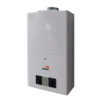
fig. 6 - Rating label
2.4 Hydraulic connections
Never support the water heater by the water/gas connections. Make
the connections in accordance with the dimensions and connections shown
in section 4.1.
There are labels on the unit identifying the 1/2” water inlet pipe (white) and the 3/4” gas
inlet pipe (yellow).
fig. 7 - Connection cards
If the water hardness is over 25ºFr ( 1ºF=10ppm CaCO3), the water
must be treated to avoid possible deposits on the unit.
2.5 Gas connection
Before making the connection, check that the unit has been prepared to
operate with the right type of fuel, and carefully clean the gas pipes to remove
any residue that might hinder correct operation. Make this connection in
accordance with the dimensions and connections in section 4.1.
1 - Connect the corresponding gas inlet (see section 4.2) in accordance with current
regulations in the country where the heater is being installed.
2 - Connect using a rigid metal pipe (connection to a gas supply network) or a
flexible, continuous stainless steel pipe (LPG installation), adding a shut-off valve
between the installation and the unit (AS CLOSE TO THE UNIT AS POSSIBLE).
3 - Once the connection to the gas network is complete, check that all gas connections are
tight. For this purpose, a tightness test must be performed. To avoid damage to the unit
due to excess pressure, leave the gas inlet valve closed.
4 - Check that the supplied pressure and gas delivery values are those indicated for the
unit's consumption. See the technical data table (section 4.5).
In installations with an approved flexible pipe for LPG, pay special
attention to the following:
• The pipe must comply with applicable regulations.
• Avoid areas with heat emissions.
• Prevent the pipe from bending or being pinched shut.
• The connections on both sides (gas valve and other components) must comply with the
regulations of the country where the heater is installed.
2.6 Air and ue gas ducts
The diameter of the pipe connecting to the flue must not be smaller than that of the pipe
connecting to the draft hood. After the draft hood, there must be a vertical segment
at least half a meter long. The dimensions and installation of the flues and the tube
connecting to them must comply with current standards.
2.6.1 FUME EXHAUST SAFETY DEVICE (fume thermostat)
• The water heater’s safety device ensures the correct exhaust of flue gases; THEREFO-
RE DO NOT DEACTIVATE IT OR CARRY OUT ANY OPERATION ON IT.
• If the safety device cuts in when the water heater is started, check the flue gas outlet,
checking the exhaust with a cold mirror or with any suitable and approved measuring
device.
• In case of a fault, only use original replacements, otherwise the safety device may not
work properly.
• Fume thermostat replacement must be carried out by qualified technicians, proceeding
as follows:
- Remove the faulty fume thermostat by undoing the 2 fixing screws.
- Install a new original thermostat.
- Fix the fume thermostat in its place without overtightening the screws.
- Check its correct operation.
NB: REMEMBER TO MAKE AN AIR INLET OPENING IN THE
ROOM WHERE THE WATER HEATER IS INSTALLED (AS RE-
QUIRED BY THE CURRENT REGULATIONS).
IF THE ABOVE INSTRUCTIONS ARE NOT OBSERVED THE-
RE MAY BE RISK OF SUFFOCATION OR POISONING DUE TO
GAS OR FUMES ESCAPING.
 Loading...