Table 2. Temperature Sensor Type:
Symbol Description Range Comment
T
T Thermocouple -200 ~ 4000 Internal Resistant 100k
R
R Thermocouple -50 ~ 1600 Internal Resistant 100k
J
J Thermocouple -200 ~ 1200 Internal Resistant 100k
WRe
WRe Thermocouple 0 ~ 2300 Internal Resistant 100k
B
B Thermocouple 350 ~ 1800 Internal Resistant 100k
S
S Thermocouple -50 ~ 1600 Internal Resistant 100k
K
K Thermocouple -200 ~ 1300 C
-328 ~ 2372 F
Internal Resistant 100k
E
E Thermocouple -200 ~ 900 Internal Resistant 100k
P10.0
P10.0 Thermo
Resistor
-200.0 ~ 600.0 Constant Output 0.2mA
P100
Pt100 Thermo
Resistor
-200 ~ 600 Constant Output 0.2mA
Cu50
Cu50 Thermo
Resistor
-50.0 ~ 150.0 Constant Output 0.2mA
Note: if a wrong probe is using, it may cause “EEE.E” error. Default is “K”
Probe Connection:
For J, K or any two wires probe, connection terminals are #9, #10
For Pt-100 probe (3 wires), the red wire is connected to #8, and the two blues are connected to
#9, #10
Output setting ‘OutY’
Fig. 2
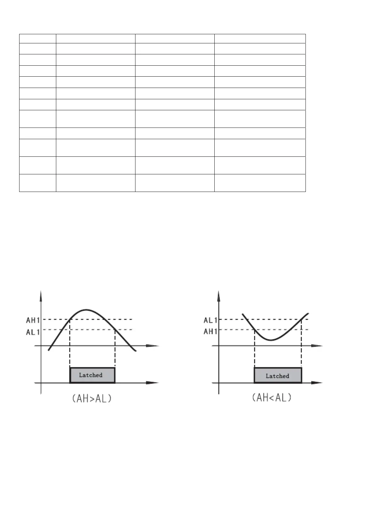
0: Relay J1 and J2 as Alarm outputs; SSR and SV Disabled, it is normally used for upper/lower
limits alarm trigger control. See Fig 2
1: Relay J1 alarm output; Relay J2 PID output controlled by SV. AH2, AL2 values are not used;
SSR control output disabled. See Fig 2
2: Relay J1 and J2 as alarm outputs; SSR PID output 8V SSR signal. Target: SV
3. J1, J2 alarm output; differential control by SSR. See Fig 3
4. J1 alarm, differential control on J2, SSR disabled, AH2, AL2 disabled. See Fig 3
 Loading...