b) To enter PID parameter setting mode press (SET), then enter code “0036”, press (SET) again.
Table 3. PID and Relevant Parameters:
Symbol Description Range Default Comment
P
Proportional Band 0.1 ~ 99.9 (%) 5.0 Note 4
I
Integration Time 2 ~ 1999 (Sec) 100 Note 5
D
Differentiation Time 0 ~ 399 (Sec) 20 Note 6
SouF
Overshoot Suppression
Coefficient
0.0 ~ 1.0 0.2 Note 7
Ot
Control Period 2 ~ 199 (Sec) 2 Note 8
Filt
Digital Filtering Strength 0 ~ 3 0 Note 9
End
Exit
P,I and d parameters control the accuracy and respond time of the temperature controller. Auto-
tuning is recommended for user who does not familiar PID control theory. P, I and d values
should only be adjusted by professionals.
Note 4
Proportional Band (P): When P increases, fluctuation of object being controlled decreases. When
P decreases, fluctuation of object being controlled increases. When P value is too small, system
may become non-converge.
Note 5
Integration time (I): its purpose is to reduce static error. When I decrease, respond speed is
faster but system is less stable. When I increase, respond speed is slower, but system is more
stable.
Note 6
Differentiation time (d): its purpose is to control in advance and compensate delay. Setting d-
value too small or too large would decrease system stability, oscillation or even non-converge.
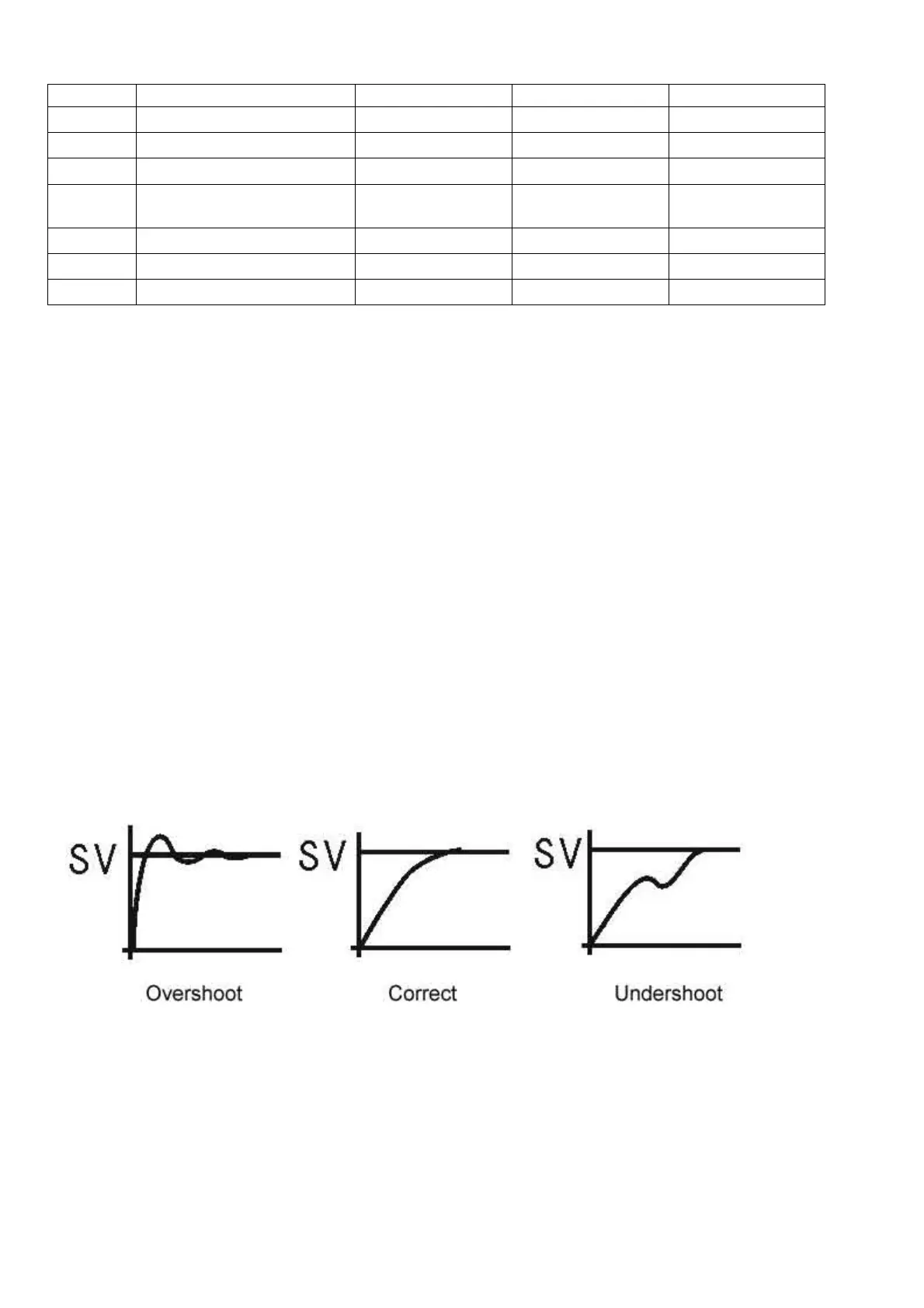
Note 7
Overshoot suppression coefficient. When overshoot exists, increase SouF. When undershoot
exists, decrease SouF.
Note 8
Control Period (ot): When ot gets smaller, heating/cooling cycle is drived faster, system respond
speed is faster. But when using contact control (Relays), contacts wear out faster.
When contact control (Relay) is used, normally set ot=5~15.
When non-contact control (SSR) is used, normally set ot=2.
 Loading...