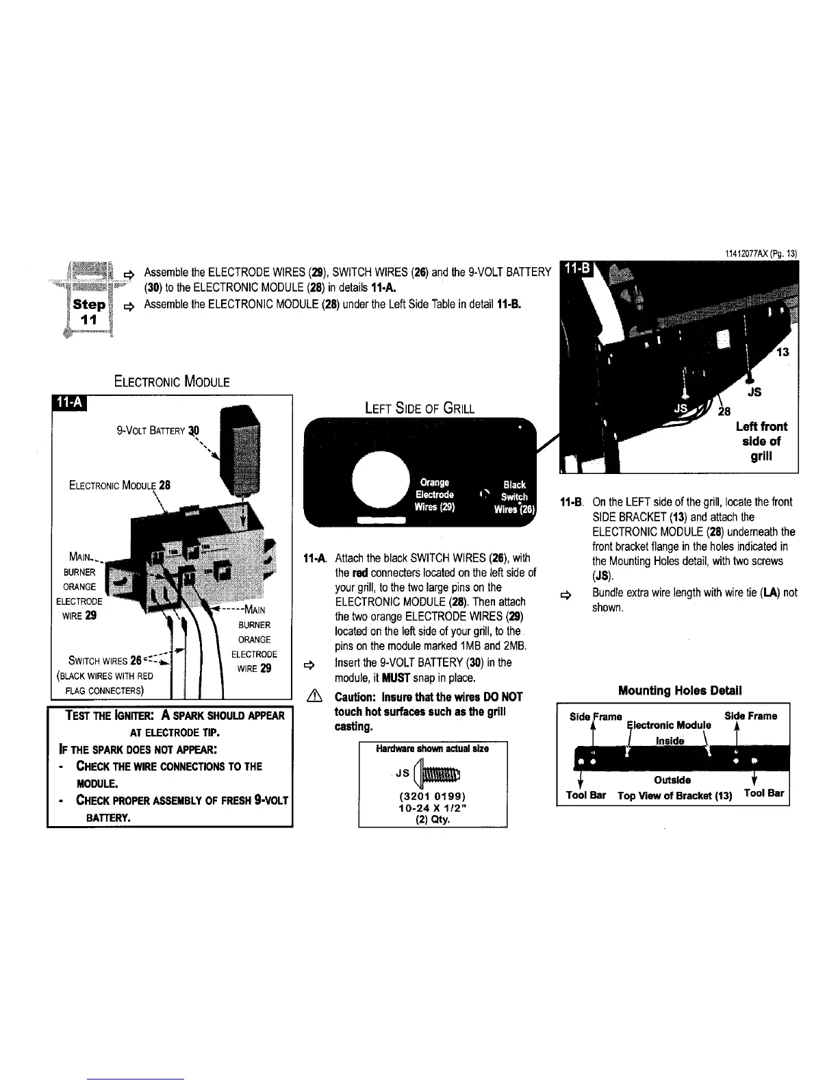
AssembletheELECTRODEWIRES(29),SWITCHWIRES(26)andthe9-VOLTBATTERY
(30)totheELECTRONICMODULE(28)indetails11-A.
AssembletheELECTRONICMODULE(28)undertheLeftSideTableindetail11-B.
11412077AX(Pg.13)
ELECTRONICMODULE
ili_;1
9-VOLT BATTERY3,0
ELECTRONICMODULE28
\
\
MAIN.,
BURNER
ORANGE
:LECTRODE
WIRE29
SWITCHWIRES26-':ZI
(BLACKWIRESWITHRED
FLAGCONNECTERS)
BURNER
ORANGE
ELECTRODE
WIRE29
TESTTHE IGNITER: A SPARKSHOULDAPPEAR
AT ELECTRODETIP.
IF THE SPARKDOES NOTAPPEAR:
CHECK THE WIRE CONNECTIONSTO THE
MODULE.
CHECK PROPERASSEMBLYOF FRESH9-VOLT
BATTERY.
LEFT SIDE OF GRILL
11-A. Attachthe black SWITCHWIRES (28),with
thered connecterslocatedon the left sideof
yourgrill, tothe two largepinson the
ELECTRONICMODULE(28), Thenattach
the twoorange ELECTRODEWIRES(29)
locatedon the left side of your grill, to the
pinson the modulemarked 1MBand 2MB.
Insertthe 9-VOLTBATTERY(30) inthe
module,it MUSTsnap in place.
/_ Caution: Insurethatthe wires DO NOT
touch hot surfacessuchas the grill
casting.
Hardwareshownactualsize
JS(_
(3201 0199)
10-24 X 112"
(2) Qty.
JS
Left front
side of
grill
11-B, Onthe LEFTside of thegrill, locatethefront
SIDEBRACKET(13)andattachthe
ELECTRONICMODULE(28) underneaththe
front bracketflange inthe holesindicatedin
the MountingHolesdetail,withtwoscrews
(JS).
=_ Bundleextrawirelengthwith wiretie (LA) not
shown.
Mounting Holes Detail
Side Frame
Inside
Outside
Tool Bar Top View of Bracket (13) Tool Bar
 Loading...