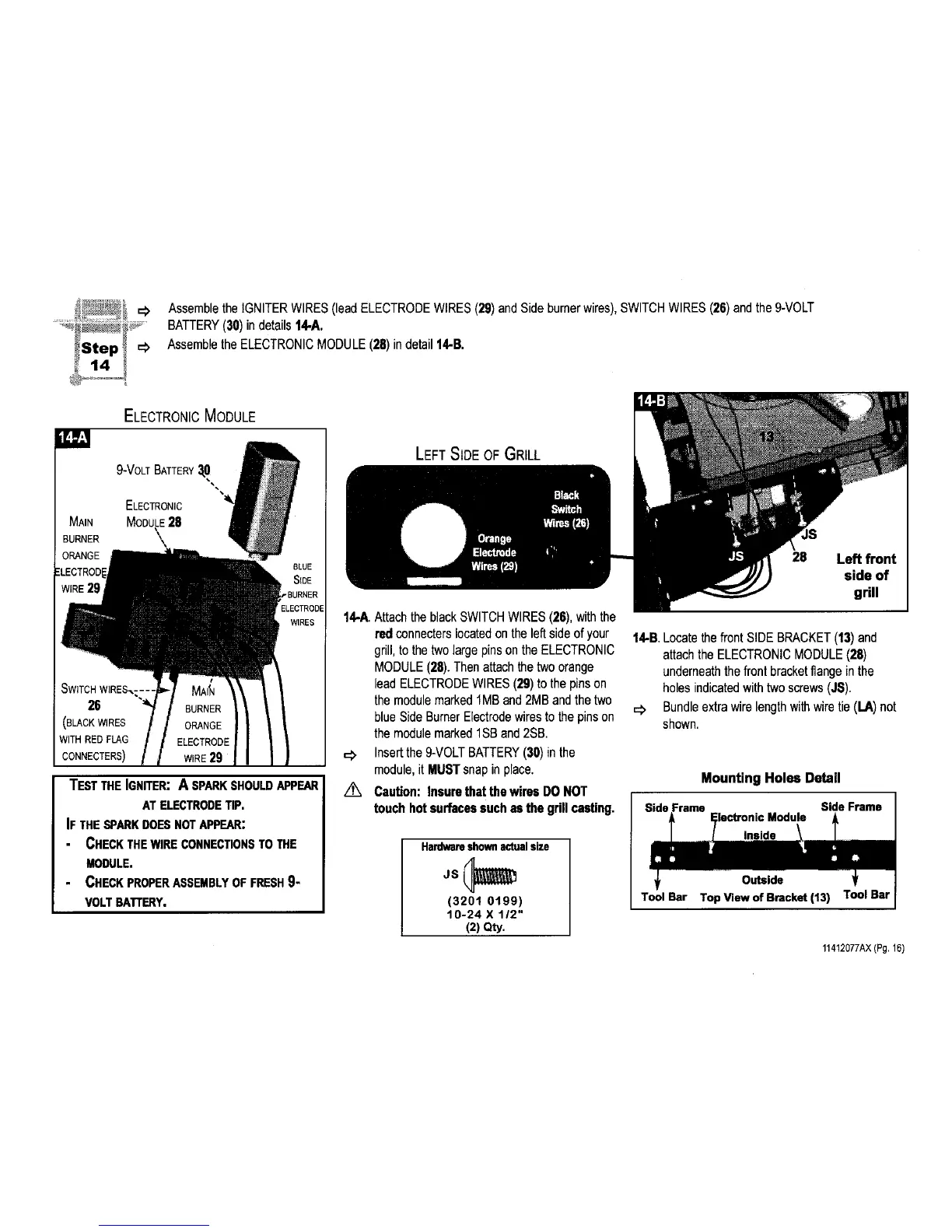
;i__,:.._.-_ =# Assemblethe IGNITERWIRES(lead ELECTRODEWIRES(29)and Side burnerwires), SWITCHWIRES (26)andthe 9-VOLT
BATTERY(30) in details 14-A.
Assemblethe ELECTRONICMODULE(28) indetail 14-B.
ELECTRONIC MODULE
9-VOLTBATTERY_[0
ELECTRONIC
MODULE28
\
WIRE29
GLUE
StDE
3URNER
ECTRODE
WIRES
26
TEST THE iGNITER: A SPARKSHOULDAPPEAR
AT ELECTRODETIP.
iF THE SPARKDOESNOTAPPEAR:
CHECK THEWIRE CONNECTIONSTO THE
MODULE.
CHECK PROPERASSEMBLYOF FRESH9-
VOLTBATTERY.
LEFT SIDE OF GRILL
14-A.Attachthe blackSWITCHWIRES(26),withthe
red connecterslocatedon the left side of your
grill,to the twolarge pins on the ELECTRONIC
MODULE(28).Thenattach the two orange
lead ELECTRODEWIRES (29)to the pinson
the modulemarked 1MBand2MB andthe two
blue Side BurnerElectrodewiresto the pinson
the modulemarked1SBand 2SB.
_, Insertthe 9-VOLTBATTERY(30)in the
module,it MUSTsnap in place.
/_, Caution: Insurethatthe wires DO NOT
touch hotsurfacessuch as the grillcasting.
Hardwareshown actual size
(3201 0199)
10-24 X 112"
(2) Qty.
28 Left front
side of
grill
14-B.Locatethe front SIDEBRACKET(13)and
attach theELECTRONICMODULE(28)
underneaththe front bracketflange in the
holes indicatedwithtwo screws(,IS).
=_ Bundleextra wire length withwire tie (I.A) not
shown.
Mounting Holes Detail
Frame Side Frame
Module
Outside
Tool Bar Top View of Bracket (13) Tool Bar
11412077AX(Pg.16)
 Loading...