Step
151
11412077AX(Pg. 17)
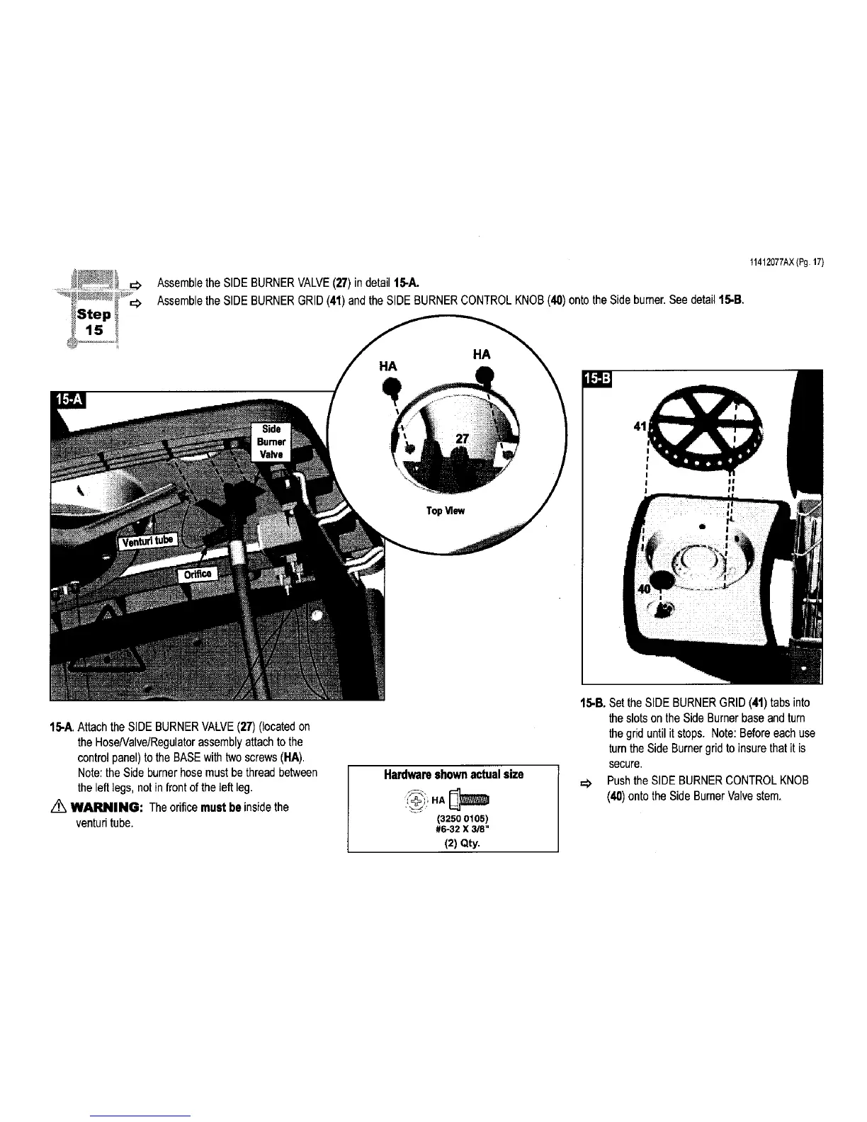
Assemblethe SIDEBURNERVALVE(27) in detail 15-A.
Assemblethe SIDEBURNERGRID(41)and the SIDE BURNERCONTROLKNOB(40)onto theSide burner.See detail15-B.
HA
HA
! I!
! I!
15-A.Attach the SIDE BURNERVALVE(27) (locatedon
the HoseNalve/Regulatorassemblyattachto the
controlpanel)to the BASEwith two screws(HA).
Note:the Side burnerhosemustbe thread between
the leftlegs, not in front ofthe left leg.
Z_ WARNING: Theorificemustbe insidethe
venturitube.
Hardwareshownactualsize
(3250 0105)
#e-32 x 3/8"
(2) Qty.
15-B. Set the SIDE BURNER GRID (41) tabs into
the slots on the Side Burner base and turn
the grid until it stops. Note: Before each use
turn the Side Burner grid to insure that it is
secure.
=:_ Push the SIDE BURNER CONTROL KNOB
(40) ontothe Side BurnerValve stem.
 Loading...