EasyManua.ls Logo

Coleman 9530A751 User Manual

Coleman 9530A751
13 pages
To Next Page IconTo Next Page
Page #1 background imageLoading...
Page #1 background image
RV Products Division
INSTALLATION INSTRUCTIONS
FOR
9330F4552 FREE DELIVERY PLENUM KITS
8330-752 CONTROL BOX KIT (12 VDC COOL ONLY)
9330C755 CONTROL BOX KIT (12 VDC HEAT READY)
8530-750 CONTROL BOX KIT (24 VAC COOL ONLY)
9530A751 CONTROL BOX KIT (12 VDC HEAT PUMP)
9430A751 ZONE CONTROL KIT (12 VDC COOL ONLY)
9430A755 ZONE CONTROL KIT (12 VDC HEAT READY)
9630A751 ZONE CONTROL KIT (12 VDC HEAT PUMP)
Airxcel, Inc.
RV Products Division
P.O. Box 4020
Wichita, KS 67204
Coleman is a registered trademark of The Coleman Company, Inc. used under license. Mach is a registered trademark.
1976N350 (9-14) PP
Question and Answer IconNeed help?

Do you have a question about the Coleman 9530A751 and is the answer not in the manual?

Coleman 9530A751 Specifications

General IconGeneral
BrandColeman
Model9530A751
CategoryControl Unit
LanguageEnglish

Summary

1. WARNINGS

WARNING – SHOCK HAZARD

Safety warning regarding electrical shock during installation.

Installation Personnel Qualification

Instructions are for qualified individuals; unlicensed persons should not service.

Component Compatibility Warning

Using untested components voids warranty and may create hazards.

2. GENERAL INFORMATION AND REQUIREMENTS

Low Temperature Sensor Installation

The low temperature sensor must be inserted into the evaporator coil.

5. CEILING PLENUM INSTALLATION REQUIREMENT

8. WALL THERMOSTATS

9. ROUTING THERMOSTAT WIRING

10. ROUTING THERMOSTAT WIRING (ZONE)

11. ROUTING 115 VAC WIRING

Wiring Sizing for Overcurrent Protection

Copper conductor sizing based on minimum overcurrent protection device amperage.

Wiring Sizing for Higher Protection Ratings

Wiring requirements based on overcurrent protection device rated higher than minimum.

12. SECURING THE UPPER UNIT TO THE ROOF

13. INSTALLING THE CONTROL BOX

A. Control Box 8330-752 Wiring Diagram

Illustration of thermostat wire connections for Control Box 8330-752.

B. Control Box 9330C755, 9530A751 Wiring Diagram

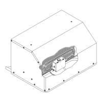
Illustration of thermostat wire connections for Control Boxes 9330C755 and 9530A751.

C. Control Box 8530-750 Wiring Diagram

Illustration of thermostat wire connections for Control Box 8530-750.

14. INSTALLING THE CONTROL BOX (ZONE)

15. INSTALLING THE HEATER ASSEMBLY

16. INSTALLING THE CEILING ASSEMBLY

Related product manuals