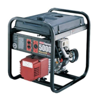
4. Turn the engine switch to the
"ON" position. See Picture 8.
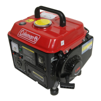
5. Pull slowly on the recoil starter until it is engaged, then pull
it briskly. See Picture 9.
6. Allow the generator ‘s engine to
warm up.
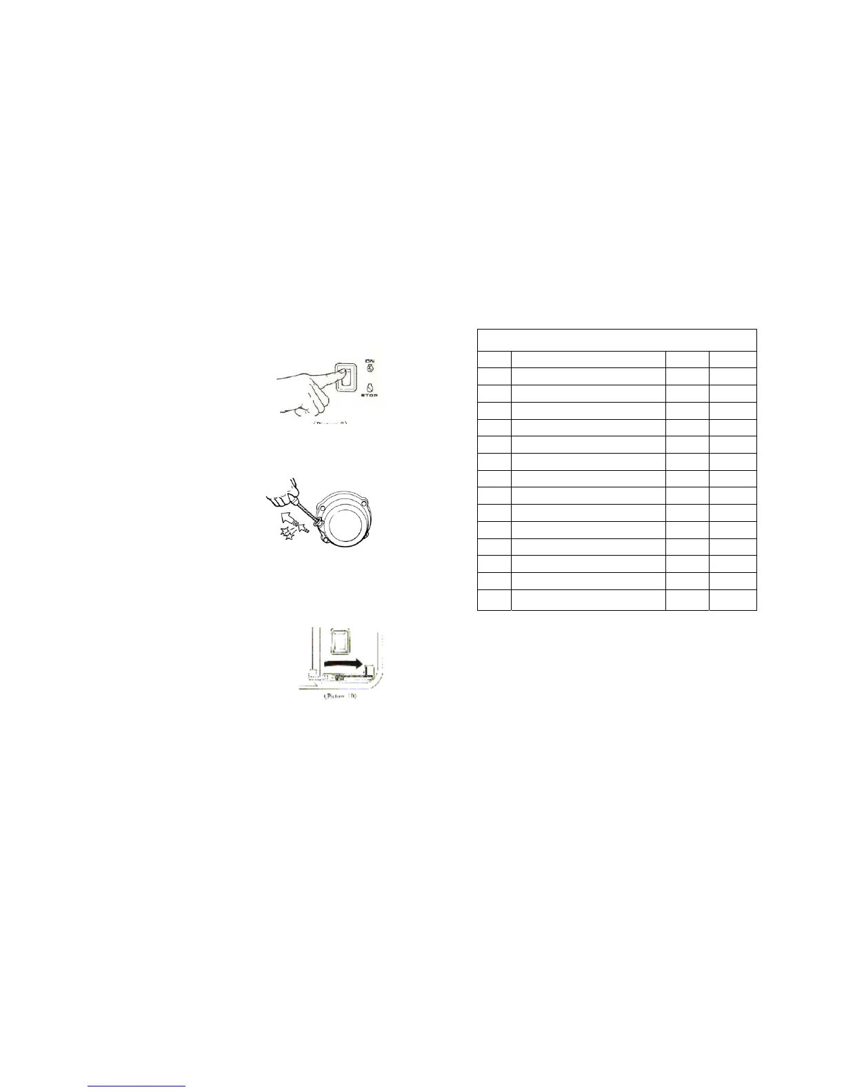
7. Now, turn the choke lever back to
its rightmost position, see Picture 10.
-10-
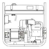
FIG. I GENERATOR
PART DESCRIPTION Q'TY SPEC
1 Stator Assy 1
2 Rotor Assy 1
3 Diode Tray 2
4 Bearing 1 6203
5 Flange Bolt 1
M8h155
6 Rear Cover 1
7 Flange Bolt 3
M6h85
8 Rectifier Stand 1
9 Rectifier 1 3510
10 Washer 1
¶5
11 Spring Washer 1
¶5
12 Bolt 1
M5h20
13 Flange Bolt 1
M6h10
14 Fan blade
1
Picture 8
Picture 9
Picture 10
-19-