This document is a user manual for the BATTLE-AX B450M-HD V14 motherboard, also referred to as the 战斧 B450M-HD 魔音版 V14. It provides comprehensive information on the motherboard's features, installation procedures, BIOS settings, and technical support.
Function Description
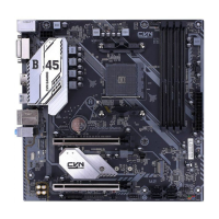
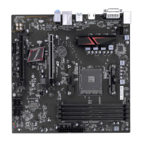
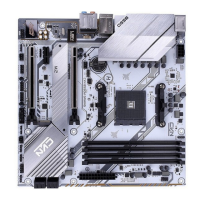
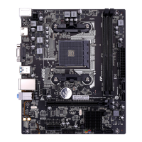
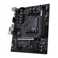
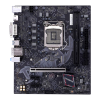
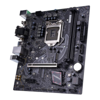
The BATTLE-AX B450M-HD V14 is a micro-ATX form factor motherboard designed for AMD processors, specifically supporting the AM4 socket. It is built around the AMD B450 chipset, offering a robust platform for various computing needs. The motherboard is equipped to handle dual-channel DDR4 memory, supporting speeds up to 3200 (OC) / 3000 (OC) / 2800 (OC) / 2666 / 2400 / 2133 MHz.
For graphics output, it includes an HDMI port, a VGA port, and a DVI port, allowing for flexible display configurations. Storage capabilities are provided through four SATA3.0 6Gb/s ports, enabling connection of multiple storage devices. The motherboard also features a high-speed M.2 slot that supports MSATA and PCI-e x4 SSDs, with data transmission rates up to 32Gb/s, compatible with 2242/2260/2280 size SSDs and NVMe standards.
Connectivity options include a gigabit LAN port for network access and a range of USB ports: two USB3.1 (Gen1) ports, two USB3.0 ports, and four USB2.0 ports. Audio is handled by an onboard 6-channel audio chipset with 3D surround sound effects. The motherboard also provides various headers for front panel audio, system panel connectors, CPU and system fans, RGB lighting, and debugging.
Important Technical Specifications
- Chipset: AMD B450
- CPU Socket: AM4
- Form Factor: mATX
- Memory:
- 2 x DDR4 DIMM slots
- Supports dual-channel DDR4 3200 (OC) / 3000 (OC) / 2800 (OC) / 2666 / 2400 / 2133 MHz
- Maximum memory capacity not explicitly stated but typically supports up to 32GB or 64GB depending on module availability.
- Expansion Slots:
- 1 x PCI Express 3.0 x16 slot
- 1 x PCI Express 3.0 x1 slot
- 1 x M.2 slot (supports MSATA and PCI-e x4 SSD, 2242/2260/2280 sizes, NVMe standard, up to 32Gb/s)
- Storage:
- Video Output:
- 1 x HDMI port
- 1 x VGA port
- 1 x DVI port
- LAN: Integrated 1000Mbps LAN chipset
- USB Ports:
- 2 x USB3.1 (Gen1) ports (rear panel)
- 2 x USB3.0 ports (rear panel)
- 4 x USB2.0 ports (rear panel)
- Internal headers for additional USB ports (2 x USB3.0, 4 x USB2.0)
- Audio: Onboard 6-channel audio chipset, supports 3D surround sound
- Internal Headers/Connectors:
- Front panel audio connector (F_AUDIO)
- System panel connector (F_PANEL)
- CPU fan header (CPU_FAN)
- System fan header (SYS_FAN)
- SPDIF header (JSPDIF)
- COM header (COM_A)
- RGB fan header (FAN_RGB_HEADER)
- Debug header (DEBUG)
- Clear CMOS jumper (CLR_CMOS)
- Speaker header (SPEAK)
- Power Connectors: 24-pin ATX power connector, 8-pin ATX 12V power connector
Usage Features
The manual details the step-by-step installation of hardware components, including the CPU, memory (DIMMs), graphics card, and storage devices.
- CPU Installation: The CPU is installed into the AM4 socket by lifting the retention lever, aligning the CPU with the triangular mark on the socket, gently placing it, and then lowering the lever to secure it. Proper cooling fan installation is also emphasized.
- Memory Installation: The motherboard supports dual-channel memory. Users should install DDR4 memory modules into DIMM1 and DIMM2 slots for optimal performance. It's crucial to use identical memory modules for dual-channel configuration and to insert them firmly until the clips lock.
- Graphics Card Installation: A PCI Express 3.0 x16 slot is provided for graphics cards. The card should be inserted into the slot and secured with the retention clip and chassis screw.
- Storage Device Installation: SATA drives connect to the SATA3.0 6Gb/s ports. The M.2 SSD is installed by first removing the screw and stud, inserting the M.2 SSD at an angle, and then securing it with the screw.
- Connecting Cables and Setting Switches: The manual provides clear diagrams and instructions for connecting various cables, including the 24-pin ATX power, 8-pin ATX 12V power, SATA cables, USB headers, front panel audio, and system panel connectors (power LED, HDD LED, power switch, reset switch).
- BIOS Setup: The BIOS (Basic Input and Output System) is a critical part of the motherboard's functionality. The manual guides users on how to enter the BIOS setup (usually by pressing DEL during boot-up) and navigate through its various menus.
- Main Menu: Displays basic system information, including BIOS vendor, core version, project version, build date, access level, total memory, and memory frequency.
- Advanced Menu: Offers advanced settings for ACPI, AMD fTPM, CPU configuration, SATA configuration, USB configuration, onboard device configuration, advanced power management, super IO configuration, hardware monitor, network stack configuration, and NVMe configuration.
- Chipset Menu: Configures settings related to the South Bridge and North Bridge, including SATA channel, SATA type, bank interleaving, channel interleaving, memory clear, IGFX multi-monitor, primary video device, integrated graphics, PSPP policy, and IOMMU.
- Security Menu: Allows setting an Administrator Password and User Password to protect BIOS settings.
- Boot Menu: Configures boot options, including boot priority, bootup numlock state, quiet boot, and full logo display.
- OC Drive (OverClock Settings): Provides options for overclocking, including DRAM voltage, VDDR voltage, CPU Fid Boost, CPU Vid Boost, memory frequency, memory command rate, memory powerdown mode, memory timing configuration (CAS latency, RAS/CAS delay, ROW precharge time, Min Active RAS, Read to Precharge, ROW cycle, Write Recover Time, RAS/RAS delay, Write to Read Delay).
- Driver Installation: The motherboard comes with a driver CD. The manual instructs users to insert the CD, and the installation program will run automatically. It emphasizes that proper driver installation is essential for the motherboard to achieve its full performance.
Maintenance Features
- CMOS Clearing: The manual describes how to clear the CMOS (Complementary Metal-Oxide-Semiconductor) settings, which can resolve issues like forgotten passwords or boot failures. This involves shorting two pins on the CLR_CMOS jumper for a few seconds after turning off the power.
- BIOS Updates: While not explicitly detailed as a maintenance step, the BIOS section notes that the BIOS version is continuously updated. Users are advised to check the company's website for the latest BIOS information, implying that BIOS updates are a part of ongoing maintenance for improved performance and compatibility.
- Troubleshooting: The technical support section provides contact information for assistance if users encounter problems that cannot be resolved using the manual.
- Environmental Protection: The manual includes a "Hazardous Substances Statement" indicating the presence of certain hazardous substances in components like the PCB, structural parts, chipsets, connectors, passive components, soldered joints, wires, and auxiliary solders/heat sinks. It specifies that these substances are within the limits set by SJ/T11363-2006, except for lead (Pb) in certain components, which is exempt under RoHS directives. This highlights the manufacturer's adherence to environmental regulations and provides transparency regarding material composition.