Carburetor Adjustment
Caution: When adjusting carburetor, always sup-
port rear of vehicle off of ground. Always support
rear of vehicle on jack stands to support vehicle
off of ground to prevent accident or injury.
Warning: While operating engine, keep hands,
tools, and clothing away from moving parts.
(Clutches, drive belt, etc.) Always, operate vehi-
cle in well ventilated area.
1. Start and warm up engine (approximately 5 minutes)
prior to adjustment.
2. Turn idle speed screw counterclockwise until throttle
lever is completely closed.
3. Rotate idle speed screw clockwise ONLY until adjust-
ment screw lightly contacts throttle lever.
Note: Never allow idle speed screw to hold throttle open.
If throttle is held open, backfire and erratic starting will
occur.
4. Holding accelerator pedal, allow engine to idle at
approximately 1,000-1,100 RPM.
5. While maintaining engine RPM, slowly rotate idle mix-
ture screw clockwise until engine begins to slow. See
Figure 39.
6. Then, turn mixture screw opposite direction (counter-
clockwise) until engine just begins to slow.
7. Rotate screw back to midpoint.
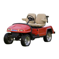
8. Place idle mixture screw limiter cap onto idle mixture
screw, with stopper tab pointed upward. See Figure
54.
FUEL PUMP
Description
The fuel pump, mounted on the main frame at the right
rear wheel creates a continuous supply of fuel from the
fuel tank to the carburetor. The pump is operated by vac-
uum pulses from the engine.
Operation
Vacuum pulses from the crankcase of the engine are
used to push and pull at an internal diaphragm. As this
diaphragm is pushed and pulled, it in turn creates high
and low pressure on the fuel side of the diaphragm.
As high and low pressure pulses occur on the fuel side
of the pump diaphragm, fresh fuel is drawn into the
pump by low pressure and pushed from the pump by
high pressure.
An integral part of the operation of the fuel pump is the
engine’s breather system located in the valve cover. See
Lubrication and Breather Systems for additional
information.
Warning: Use care when working with fuel sys-
tem. Clean up any spilled fuel immediately
before continuing. Never service or repair fuel
system near open spark or flame.
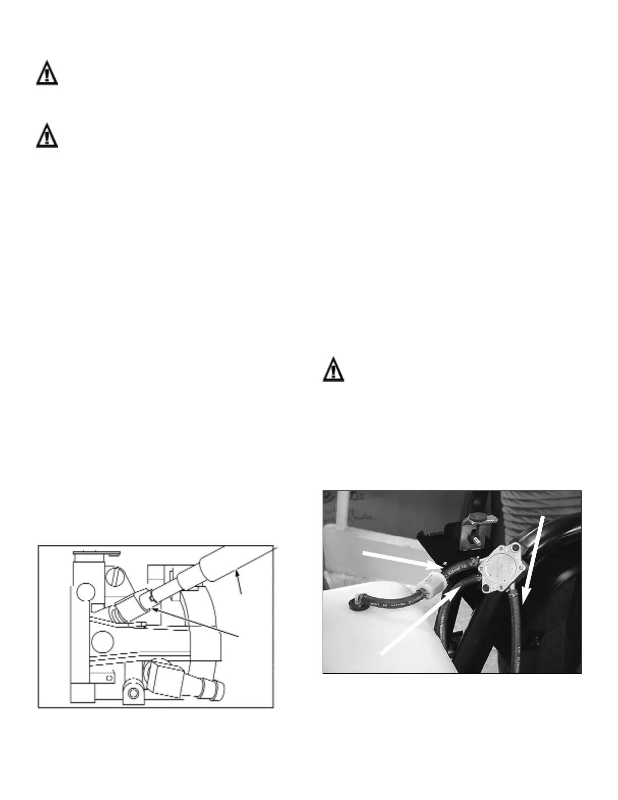
Fuel Pump Removal
1. Carefully, disconnect the single vacuum hose from
top of engine and two fuel hoses from fuel pump.
See Figure 55.
2. Remove two screws holding fuel pump to frame, and
remove fuel pump.
7-25
Figure 54 - Installing Limiter Cap
Figure 55 - Remove Fuel and Vacuum Line
Fuel In
Vacuum
From
Engine
Fuel Out
Knock Out
Pin Tool
#19135
Limiter
Cap
 Loading...