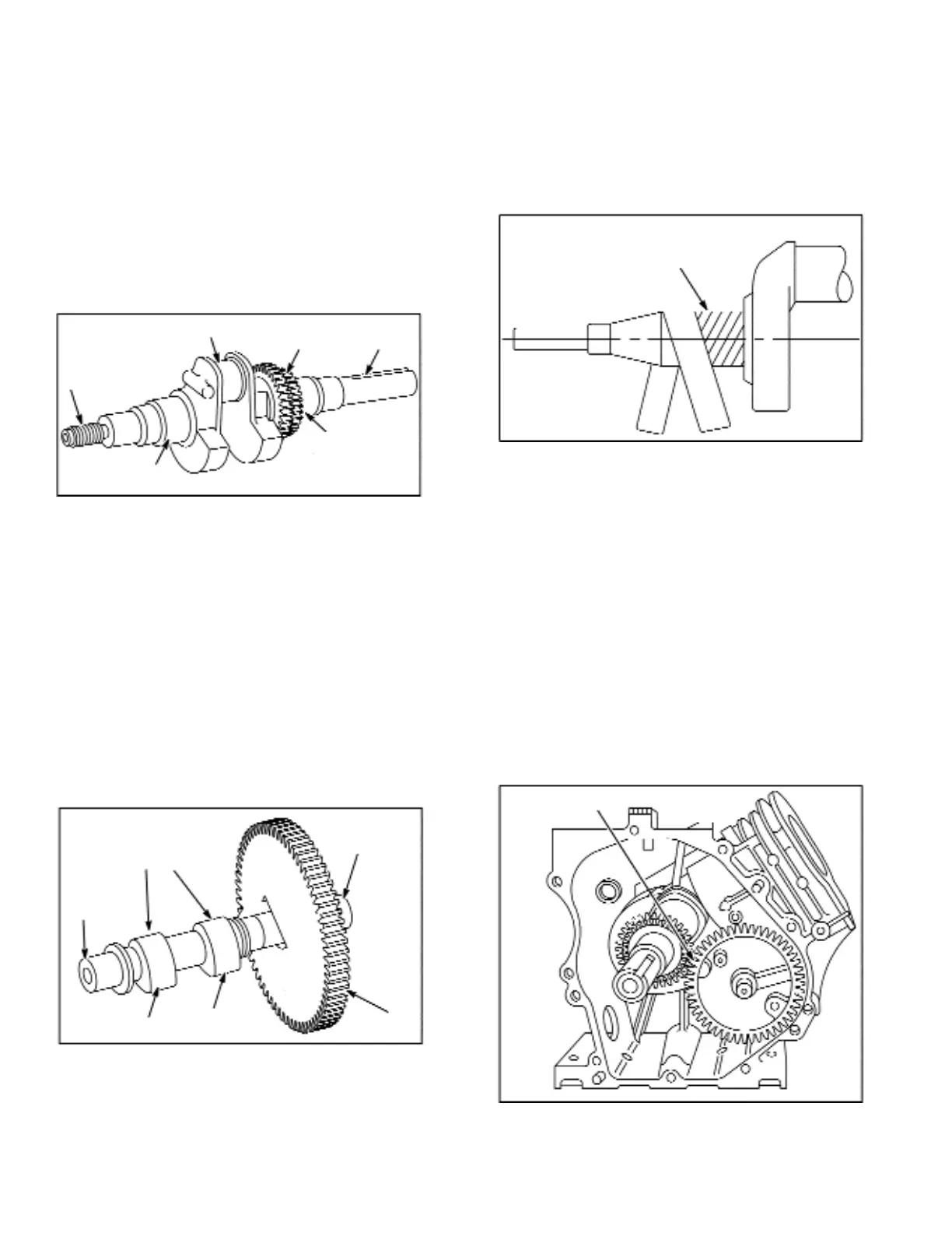
Inspect Crankshaft
Table 19 shows reject sizes of various wear points of the
crankshaft. Discard crankshaft if worn smaller than size
shown. Keyways should be checked to be sure they are
not worn or spread. Remove burrs from keyway edges to
prevent scratching bearing. Figure123 shows various
points to be checked on crankshaft.
Note: Do not straighten bent crankshaft.
Check timing gears for chipped or cracked teeth and key-
way for wear. Replace timing gear, if damaged. If timing gear
is chipped or cracked, also check cam gear for damage.
Note: .020" (.51 mm) undersize connecting rods may be
obtained for use on reground crankpin journals. Complete
instructions are included with undersize rod. (See
Illustrated Parts List to find appropriate undersize con-
necting rod.)
For grinding dimensions of crankpin journal, see Table 20.
Check Cam Gear
Inspect gear teeth for wear and nicks, Figure 124. Cam
gear, cam gear journals, and lobe rejection sizes are
shown in Table 21. See Figure 124 for other areas to be
checked for wear.
Polish Crankshaft Journals
Polish crankshaft with crocus 200 grit cloth until polish
lines are uniform over entire journal, Figure 125. Direction
of polish lines must be as shown in Figure 125. It is impor-
tant that crankshaft journal be thoroughly cleaned. Wash
journal with a solvent such as kerosene to remove emery
residue.
Install Crankshaft
1. Install intake and exhaust valve tappets first.
2. Supporting both ends of crankshaft, install in cylinder.
3. Install connecting rod on crankshaft, page 7-46.
4. Install slip fit timing gear (if removed) with inner cham-
fer toward crankpin. This assures timing mark will be
visible.
5. Install counterbalance shaft and gear, page 7-58.
Install Cam Gear
Install cam gear, making sure tappets clear cam lobes.
Timing marks must align. See Figure 126.
7-48
Figure 123 - Crankshaft Check Points, Typical
Figure 125 - Polishing Journal
Figure 126 - Aligning Timing Marks, Typical
Figure 124 - Cam Gear Check Points, Typical
Threads
Crankpin
Timing
Gears
Keyway
PTO
Journal
Mag
Journal
Mag
Journal
Cam
Lobes
PTO
Journal
Gear Teeth
Exhaust
Intake
Polish
Lines
Timing Marks
 Loading...