Installation
and
Instruction Guide
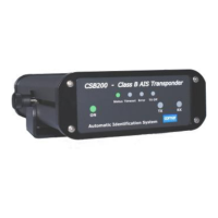
CSB200
Class B AIS Transponder
CSB200 Class B AIS
R2.0 2
GENERAL WARNINGS................................................................ 3
INTRODUCTION........................................................................... 6
AUTOMATIC IDENTIFICATION SYSTEM (AIS)................................... 6
INFORMATION TRANSMITTED AND RECEIVED ................................. 7
INSTALLING THE CSB200 UNIT................................................. 8
PACKING LIST.............................................................................. 8
ELECTRICAL CONNECTIONS ......................................................... 8
GPS ANTENNA............................................................................ 9
VHF ANTENNA............................................................................. 9
DATA CONNECTION ................................................................... 11
PROGRAMMING THE CSB200.................................................. 13
PROAIS PROGRAM .................................................................... 13
STATIC DATA............................................................................. 16
GPS STATUS ............................................................................ 19
DIAGNOSTICS ............................................................................ 20
SERIAL DATA............................................................................. 23
OTHER VESSELS ....................................................................... 24
SAFETY MESSAGES ................................................................... 25
COMMANDS............................................................................... 26
USING THE CSB200 .................................................................. 28
SWITCHING ON .......................................................................... 28
WARNING AND FAULT STATES.................................................... 28
LED INDICATORS....................................................................... 29
LED STATUS INDICATORS.......................................................... 31
TROUBLESHOOTING GUIDE.................................................... 33
SERIAL DATA INTERFACE....................................................... 36
SERIAL PORT INPUT/OUTPUT ..................................................... 36
NMEA MESSAGES .................................................................... 37
PRODUCT SPECIFICATION...................................................... 42
GLOSSARY................................................................................. 45
www.busse-yachtshop.de | info@busse-yachtshop.de