P.2
◆
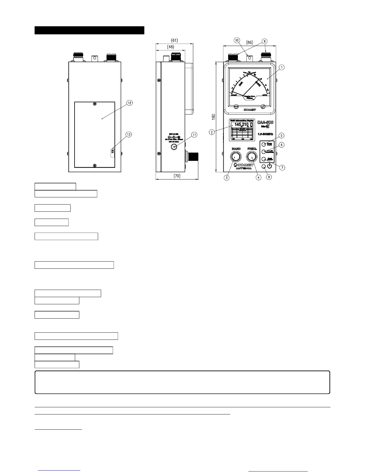
Panel/Case Parts and Descriptions
①
Display Meter This Cross Meter displays both SWRand Impedance simultaneously.
②
Multi-function Display The color LCD (Liquid Crystal Display) shows frequency, amateur band, and SWR data
(impedance (Z)/resistance (R)/reactance (X)), and also can provide a swept-frequency SWRgraph.
③
BAND Knob This knob is used to select the frequency band within the range 1.8 to 500 MHz. Clockwise rotation of
this knob selects a higher frequency band. It is also used for setting of the APO (Automatic Power Off) function.
④
FREQ.Knob This knob is used to set the frequency within the selected amateur band. Clockwise rotation increases
the frequency, while counter-clockwise rotation lowers the frequency.
⑤
SWEEP/CENTERButton In the “Normal” mode, pressing this button starts an SWRsweep of the band.
・
When in the SWRGraph mode, pressing this button sets the current display frequency to be the center frequency of
the graph. In this mode, rotate the (3)BAND knob to adjust the Sweep width; press the (6) A.P.OFF/WIDTH button to
confirm. Now rotate the (4) FREQ knob to create and display the SWRplot.
⑥
A.P.-OFF/BANDWIDTH Button In the “Normal” mode, press and hold in this button for three seconds to allow setting
of the Auto Power Off feature’s time interval.
・
In the “Manual” plot mode, pressing this button allows you to set the
bandwidth of the SWR Sweep.
・
While in the “Manual” plot mode, pressing this button allows you to change the color
of the SWRGraph.
⑦
GRAPH ON/OFF Button Press this button to switch between the “Normal” mode and the SWRGraph modes.
⑧
POWERButton This is the main Power On/Off button for this device. Press once to turn the unit on, and again to
turn it off.
⑨
RF Connectors These are the coaxial jacks used for connection to the coaxial cable. The left connector is an “M”
(“UHF”) type (used for 1.8-300 MHz), while the right jack is Type N, used for 300-500 MHz. Switching is automatic,
based on the Band setting.
⑩
Hand Strap Mounting Bracket You may connect a commercially-available hand strap here. As the diameter of the
mounting hole is greater than 1 mm, a sturdy strap (highly recommended) may be attached.
⑪
External DC Power Terminal External DC (8-16V) may be connected here. The center pin is positive (+).
⑫
Battery Case This is the housing for six AA cells. Please install them according to the inscription inside the case.
⑬
Charge Switch (Inside Battery Case) This is the switch for enabling/disabling trickle charging of Ni-MH cells, if used.
(
※
) Trickle charging is useful to help maintain a full charge on your battery by compensating for the slight
self-discharge that can occur even without a load being placed on the batteries
Before You Start
This instrument has been calibrated with the unit being held horizontally, with the meter facing up. The discussion
below is an operating example; the parameters you set may affect the actual results.
When using Alkaline or similar batteries, be sure to set this switch to the OFF position. In the event of
battery leakage, serious damage to this unit may occur if the switch is set to ON during use.
You created this PDF from an application that is not licensed to print to novaPDF printer (http://www.novapdf.com)
 Loading...