EasyManua.ls Logo

ComfortStar 18 - User Manual

Default Icon
27 pages
Print Icon
To Next Page IconTo Next Page
Loading...
INSTALLER’S GUIDE
CONDENSING UNITS
Split System Air Conditioner
1.5-5 Tons
UP TO 15.2 SEER2
R410a
Thank you very much for purchasing our product.
Before using your unit, please read this manual carefully and keep it for future reference.
The figure shown in this manual is for reference only and may be slightly different from the actual product.
Question and Answer IconNeed help?

Do you have a question about the ComfortStar 18 and is the answer not in the manual?

Summary

Key to Symbols and Safety Instructions

Key to Symbols

Explains warning symbols and keywords like DANGER, WARNING, CAUTION, NOTICE.

Safety

General safety precautions and warnings for installation and service.

Unit Location Considerations

Unit Dimensions

Provides dimensions for different unit models.

Location Restrictions

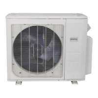
Details clearance requirements and placement advice for outdoor units.

Unit Preparation

Preinstallation

Steps for pre-installation checks and required instruments for R410A.

Setting Up the Unit

Pad Installation

Guidelines for installing the unit on a support pad or concrete slab.

Refrigerant Line Considerations

Service Valve Connection Sizes

Specifies connection sizes for service valves for different models.

Refrigerant Line Sizes

Details recommended suction and liquid line sizes for various models.

Refrigerant Piping Limits And Required Refrigerant Line Length

Lists maximum vertical and total equivalent lengths for refrigerant lines.

Refrigerant Line Insulation

Emphasizes insulating suction lines and avoiding metal-to-metal contact.

Reuse Existing Refrigerant Lines

Precautions for using existing refrigerant lines in retrofit applications.

Refrigerant Line Routing

Precautions

Advises on routing lines to prevent noise and ensure proper installation.

Refrigerant Line Brazing

Braze The Refrigerant Lines

Step-by-step guide for brazing refrigerant lines with nitrogen purge.

Refrigerant Line Leak Check

Check For Leaks

Procedure to pressurize lines with nitrogen and check for leaks with soapy solution.

Evacuation

Evacuate the Refrigerant Lines and Indoor Coil

Instructions for evacuating the system to a specific micron level.

Service Valves

Open the Service Valves

Detailed steps and warnings for opening service valves.

Electrical - Low Voltage

Low Voltage Maximum Wire Length

Table showing max wire lengths for low voltage connections.

Low Voltage Hook-up Diagrams

Diagrams illustrating low voltage wiring for different thermostat types.

Electrical - High Voltage

High Voltage Power Supply

Guidelines for high voltage power supply, including safety warnings.

High Voltage Disconnect Switch

Instructions for installing a disconnect switch at the outdoor unit.

High Voltage Ground

Requirements for grounding the outdoor unit according to codes.

Start Up

System Start Up

Steps to follow after installation to start the system.

System Charge Adjustment

Charging: Weigh-In Method

Procedure for charging the system using the weigh-in method.

Suction Line Pressure Charging And Refrigerant Adjustment In Cooling

Method for charging and adjusting refrigerant based on suction pressure.

System Operation and Troubleshooting

Protection Function

Explains various protection mechanisms like high pressure and temperature cutoffs.

Two-stage Compressor (61 K AC only)

Details operation of the two-stage compressor controlled by Y1 and Y2.

Temperature Sensor Resistance Table

Table correlating temperature with resistance for sensors.

Electrical Data Table

Provides electrical data like ampacity and circuit protector ratings for models.

Troubleshooting Table

A guide to diagnose system faults by checking components and modes.

Fault Code Table

Lists error codes from motor driver and main control modules.

Warranty

Maintenance

Guidance on cleaning coils and maintaining the unit.

Removing and Installing The Cover Plate

Steps for safely removing and reinstalling the control box cover plate.

Changing Motor

Detailed steps for replacing the fan motor, including safety precautions.

Matching Table and Checkout Procedures

Operational and Checkout Procedures

Final checks for system operation and performance after installation.

Overview

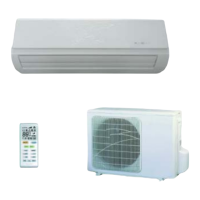
This document serves as an installer's guide for ComfortStar® Split System Air Conditioner Condensing Units, ranging from 1.5 to 5 tons, with up to 15.2 SEER2, and utilizing R410a refrigerant. It provides comprehensive instructions for the proper installation, adjustment, and operation of these units, emphasizing safety, technical specifications, usage, and maintenance.

Function Description

The ComfortStar® condensing units are designed as part of a split system air conditioning setup, working in conjunction with an indoor coil and air handler to provide cooling for residential or commercial spaces. The units utilize R-410A refrigerant, which operates at higher pressures than R-22, requiring specialized service equipment. The system's primary function is to transfer heat from the indoor environment to the outdoors, thereby cooling the conditioned space. For 61K AC systems, a two-stage scroll compressor is featured, allowing for more precise temperature control and potentially greater energy efficiency by operating at different capacities based on demand. The control system manages the compressor and outdoor fan motor operations, including protection functions against high discharge temperature and high pressure.

Important Technical Specifications

  • Capacity: 1.5 to 5 tons (18K to 61K models).
  • SEER2 Rating: Up to 15.2 SEER2.
  • Refrigerant Type: R-410A.
  • Refrigerant Oil: POE oil (VG74 or equivalent).
  • Pressure Ratings for Manifold Sets: 800 PSIG high side, 250 PSIG low side.
  • Hose Service Pressure Rating: 700 PSIG.
  • Unit Dimensions (H x W x L in inches):
    • 18K: 24-15/16 x 23-5/8 x 23-5/8
    • 24K: 24-15/16 x 28 x 28
    • 30K: 33-3/16 x 28 x 28
    • 36K: 24-15/16 x 29-1/8 x 29-1/8
    • 42K/48K/60K/61K: 33-3/16 x 29-1/8 x 29-1/8
  • Service Valve Connection Sizes:
    • Liquid Line: 3/8" (standard for all models), 5/16" or 1/2" (optional for some models).
    • Suction Line: 3/4" (standard for 18K-36K), 7/8" (standard for 42K-61K), 5/8" or 1-1/8" (optional for some models).
  • Refrigerant Piping Limits: Maximum equivalent length varies by model and liquid line size, ranging from 10 to 150 feet. Maximum vertical length also varies, from 4 to 60 feet.
  • Low Voltage Wiring:
    • 18 AWG: 150 Ft. Max. Wire Length
    • 16 AWG: 225 Ft. Max. Wire Length
    • 14 AWG: 300 Ft. Max. Wire Length
  • Electrical Data (Minimum Circuit Ampacity / Maximum Circuit Protector):
    • 18K: 11.6 A / 15 A
    • 24K: 14.7 A / 20 A
    • 30K: 15.8 A / 25 A
    • 36K: 21 A / 35 A
    • 42K: 24.9 A / 45 A
    • 48K: 25.3 A / 45 A
    • 60K: 35.1 A / 60 A
    • 61K: 38.9 A / 60 A
  • Temperature Sensor Resistance Table: Provides resistance values (in KΩ) for various temperatures (°F), crucial for troubleshooting and system diagnostics.
  • Fault Code Table: Categorizes fault codes for both motor driver module (LED1) and main control module (LED2), indicating issues such as power supply failure, sensor failures, motor errors, and communication errors.

Usage Features

  • Installation Flexibility: Units can be installed on a support pad or rooftop, with specific guidelines for elevation (3-12 inches) and clearances (minimum 60 inches above, 12 inches from shrubbery/walls, 24 inches between units) to ensure proper airflow and drainage.
  • R-410A Compatibility: Requires R-410A approved service equipment, including gauge sets, hoses, refrigerant containers, recovery systems, and leak detectors.
  • Charging Methods:
    • Weigh-In Method: Used for initial installation or when replacing system charge, especially when power is unavailable or outdoor/indoor temperatures are outside the range for suction line pressure charging.
    • Suction Line Pressure Charging: Recommended for charging above 55°F outdoor ambient temperatures, with specific instructions for calculating refrigerant adjustments based on line length and lift.
  • Two-Stage Compressor (61K AC only): Allows for modulated cooling capacity, controlled by Y1 (first stage) and Y2 (second stage) thermostat inputs, enhancing comfort and efficiency.
  • Protection Functions: The unit incorporates safety features such as discharge temperature protection (compressor stops if >239°F, restarts if <167°F) and high pressure protection (compressor and outdoor fan motor stop if >609 PSIG for 18K-30K or >638 PSIG for 36K-61K, restarting if <464 PSIG after a 3-minute delay). The compressor also won't start if ambient temperature (T4) is <32°F and restarts if ≥41°F.
  • Low Voltage Hook-up Diagrams: Detailed wiring diagrams are provided for both one-stage and two-stage heat thermostats, ensuring correct electrical connections.

Maintenance Features

  • Coil Cleaning: Regular cleaning of indoor and outdoor coils is essential to maintain efficiency, using a brush, vacuum cleaner attachment, or other suitable means.
  • Filter and Blower Motor Maintenance: Refer to the furnace or air handler instructions for specific filter and blower motor maintenance.
  • Drain Pan Inspection: The indoor coil and drain pan should be inspected and cleaned regularly to ensure proper drainage.
  • Refrigerant Line Integrity: If reusing existing refrigerant lines, ensure they are correctly sized, free of leaks, acid, and oil, and that all joints are brazed, not soldered.
  • Motor Replacement: Step-by-step instructions are provided for changing the outdoor fan motor, emphasizing safety precautions like disconnecting power and proper handling of fan blades.
  • Troubleshooting Table: A comprehensive table helps diagnose system faults by correlating symptoms (e.g., head pressure too high/low, compressor won't start) with primary and secondary causes related to the refrigerant circuit, electrical components, and defrost system.
  • Fault Code Diagnostics: LED indicators on the motor driver and main control modules provide specific fault codes, allowing for quick identification of system issues.
  • Warranty Registration: Owners are encouraged to process warranty cards and/or online registration.

Safety Information

The manual highlights several critical safety warnings:

  • Qualified Personnel: Installation, adjustment, and operation should only be performed by qualified, licensed service personnel.
  • Hazardous Voltage: Disconnect all electric power before servicing to prevent electrical shock or death.
  • R-410A Pressure: R-410A operates at high pressures; use only approved service equipment.
  • Hygroscopic Oil: POE oil readily absorbs moisture; keep the system sealed and replace compressor oil if exposed to atmosphere for more than 4 hours.
  • Brazing: All refrigerant line joints must be brazed, not soldered.
  • Refrigerant Recovery: Recover refrigerant to relieve pressure before opening the system.
  • Grounding: Reconnect all grounding devices after service.
  • Hot Surface: Avoid touching the top of the compressor due to high temperatures.
  • Refrigerant Venting: It is unlawful to knowingly vent, release, or discharge refrigerant into the open air.
  • Low/High Voltage Separation: Low voltage lines must be connected inside the outdoor unit case through the control wiring channel on the right, and high voltage lines through the power wiring channel on the left, to prevent personal injury from mixed channels.

ComfortStar 18 Specifications

General IconGeneral
BrandComfortStar
Model18
CategoryAir Conditioner
LanguageEnglish

Related product manuals