This document outlines the service and maintenance procedures for the DC Inverter R410A Air Conditioners & Heat Pump, Service Manual 2014.
Function Description
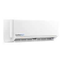
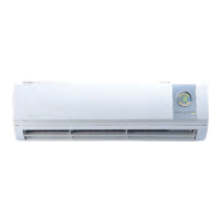
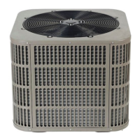
The DC Inverter R410A Air Conditioners & Heat Pump system is designed for both cooling and heating applications, utilizing R410A refrigerant. The system comprises indoor and outdoor units, with various models available to suit different capacity requirements. The indoor units are available in different sizes (24, 36, 48, 60) with corresponding dimensions and liquid/vapor line connections. Outdoor units also come in different capacities (AC, HP) with specific dimensions and refrigerant connections (liquid and suction lines). The system incorporates a refrigerant cycle diagram for both cooling-only and heat pump models, detailing components like the condenser, evaporator, compressor, expansion valve, and various sensors (condenser temp., pressure, discharge temp., ambient temp.). Wiring diagrams are provided for PSC motor A/C systems and H/P systems, as well as ECM motor A/C and H/P systems, including details for optional electric heat kits.
Important Technical Specifications
Dimensions:
- Indoor Units:
- Model 24: Height 46-1/2", Width 19-5/8", Depth 21-5/8". Liquid line 3/8", Vapor line 3/4".
- Model 36: Height 54-1/2", Width 22", Depth 24". Liquid line 3/8", Vapor line 3/4".
- Model 48: Height 54-1/2", Width 22", Depth 24". Liquid line 3/8", Vapor line 7/8".
- Model 60: Height 54-1/2", Width 22", Depth 24". Liquid line 3/8", Vapor line 7/8".
- Outdoor Units:
- Models 24/36: Height 24-15/16", Width 29-1/8", Length 29-1/8". Liquid line 3/8", Suction line 3/4".
- Models 48/60: Height 33-3/16", Width 29-1/8", Length 29-1/8". Liquid line 3/8", Suction line 7/8".
Refrigerant: R410A.
Electrical Specifications: Wiring diagrams specify connections for main board, transformer (output 24V-1.5A), fan motor, and optional electric heat kits. Power wiring for 5kW, 7.5kW, 10kW, 15kW, and 20kW heat kits is detailed, including circuit breaker and fuse link requirements.
Operational Characteristics:
- Cooling: Room temperature ≥17°C (62°F), Outdoor temperature 10°C ~ 48°C (50°F ~ 118°F).
- Heating: Room temperature <30°C (86°F), Outdoor temperature -15°C ~ 30°C (5°F ~ 86°F).
Control System: DC Inverter technology, with a main control board that includes various ports for sensors (condenser temp., ambient temp., pressure, radiator temp., discharge temp.), EXV drive, high pressure switch, and communication. Error codes (E4, E5, E6, E7, Eb, F1, F3, F4, F5, H0, H3, H4, H5, H6, H8, Hb, HH, P0, P1, P2, P3, P4, P5, P6, PH, C3, CE) are defined for troubleshooting.
Usage Features
Installation:
- Outdoor Unit: Requires a minimum of 18 inches clearance from coil face. Should be installed on a solid base at ground level, ensuring it is level and stable. Elevated installation is recommended in areas with potential snow accumulation. Tie-down methods are provided to secure the unit.
- Refrigerant Piping: Proper sizing of liquid and suction lines is crucial, with guidelines for maximum interconnecting line length (150 feet) and vertical lift (minimum 15 feet). Brazing procedures must be followed carefully, using dry nitrogen to prevent oxidation.
- Indoor Unit: Vertical upflow configuration is standard, with options for horizontal right or left airflow. Ductwork must comply with NFPA 90A, NFPA 90B, and local ordinances.
- Electrical Connections: All field wiring must use copper conductors only and comply with local, national, and safety codes. Proper grounding is essential. Power wiring, control wiring, and thermostat wiring diagrams are provided for various system configurations.
Operation:
- Defrost Cycle: Initiates when compressor operates, T4 is >-2°C, and T3 is <0°C for 40 minutes, or when T4 is <-2°C and T3 is <0°C for 50 minutes. Also, when compressor operates, T3 is <0°C for 30 minutes. The cycle lasts for 10 minutes and stops if T3 ≥25°C.
- Compressor Crankcase Heater (CCH): Optional for heat pump models, it prevents refrigerant migration during off-cycles. It must be energized for at least 12 hours before compressor start-up if the outdoor temperature is <3°C and the compressor has been off for more than 3 hours.
- Oil Return Program: Automatically activates when compressor frequency is below minimum oil return frequency, running for 5 minutes after 8 hours of continuous operation.
Maintenance Features
Safety Precautions:
- Always disconnect power before servicing.
- Use appropriate personal protective equipment.
- Follow all warnings and cautions regarding high voltage, refrigerant handling, and sharp edges.
General Maintenance:
- Filter Cleaning/Replacement: Regular cleaning or replacement of air filters is recommended to maintain optimal performance and indoor air quality.
- Drain Pan/Line Maintenance: Ensure condensate drain lines are clear and properly sloped to prevent blockages and water damage.
- Refrigerant Charge: Check and adjust refrigerant charge according to the charging chart in the manual, especially after installation or component replacement.
Troubleshooting:
- Error Display: The outdoor unit displays error codes (e.g., E4 for environmental temperature sensor fault, E5 for voltage protection, H0 for communication fault).
- Diagnostic Flowcharts: Detailed flowcharts are provided for diagnosing and resolving common issues, including sensor errors (T3, T4, T5, Tf), communication errors, compressor over-current protection, fan motor errors, voltage protection, radiator temperature protection, low pressure protection, high pressure protection, and compressor liquid return.
- Sensor Resistance Tables: Tables are provided to compare temperature, resistance, and voltage for T3/T4 and T5/Tf sensors, aiding in diagnosis.
Component Replacement:
- Outdoor Unit Electronic Control Box: Step-by-step instructions for disconnecting the cover, replacing the old board with a new one, and reinstalling the cover.
- Fan Motor: Instructions for removing fan nuts, fan blade, and motor for replacement.
- Compressor: Procedures for checking compressor insulation and coil integrity, and for replacement if necessary.
- Sensors: Instructions for re-inserting or replacing faulty sensors.