id8 data sheet – V1.0/1023 commend.com P 11 / 12Subject to change without notice.
MOUNTING
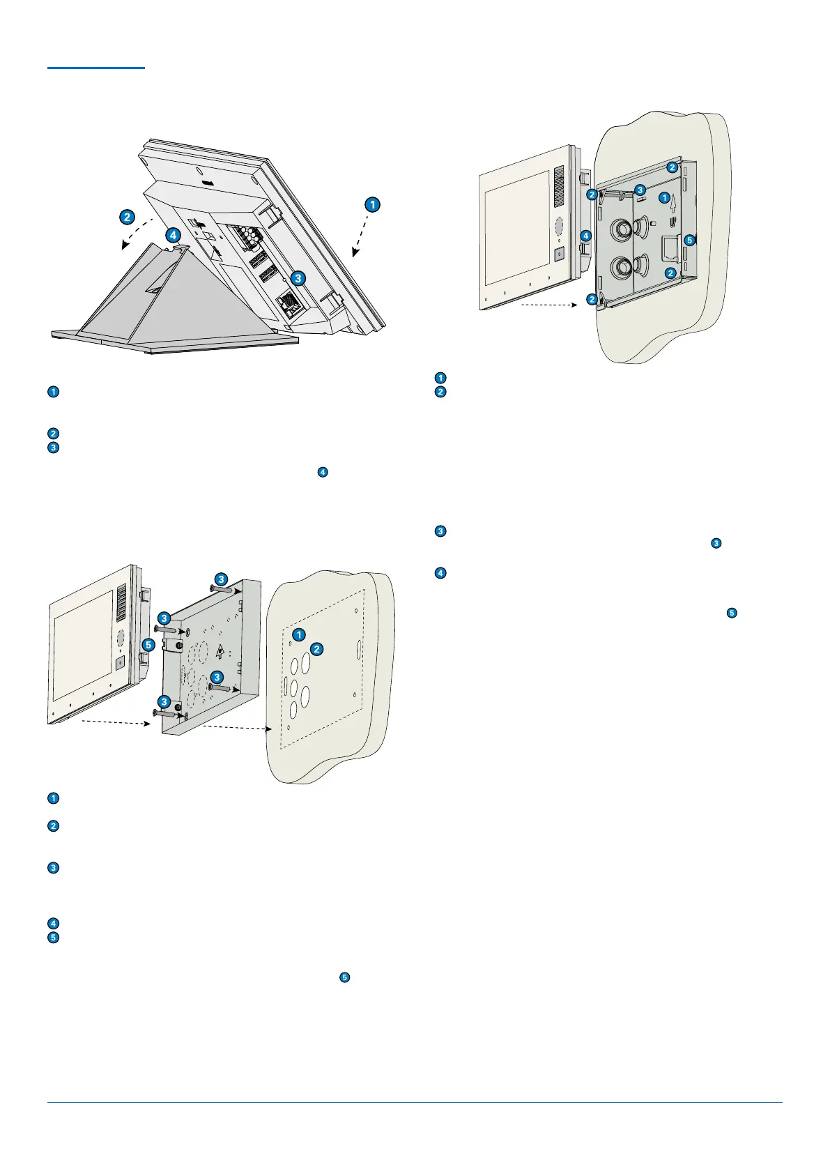
WALL MOUNTING WITH ID8 SH
WALL MOUNTING WITH ID8 FB
Make sure the arrow on the mounting frame point upwards.
Install the mounting box to the wall as shown at “Dimensions”. Press
the 4 claw clamps on the sides of the mounting box outwards and
tighten them using the corresponding screws (TX10).
(Optional:) Mount the audio induction loop kit AFIL-USB on the
mounting points (see short reference “AFIL-USB”).
(Optional:) Mount the various accessories (e.g. EB3E2A-AUD) on the
mounting points (see corresponding reference).
(Optional:) Place the CAT. crimp jack MODJ8-8KUPPL in the sheet
metal flap and fixate using cable ties. Mount the CAT. crimp jack
onto the open end of a CAT. cable.
Connect the required cables (Ethernet and USB or I/O cables, if
needed). Fixate the cables to the sheet metal bridges
using cable
ties, if needed.
Insert the device into the mounting box and press until the 4 locking
latches on the right and left side of the device lock in.
To unmount the device, push firmly onto the locking latches
and
gently remove the device. If necessary, use a tool (i.e. a screwdriver) to
push the locking latches in.
Drill four holes in the wall (see “Dimensions”) and insert the supplied
dowels.
Cut out one of the provided cable entries depending on cable
supply and guide the required cables through those entries
(Ethernet and USB or I/O cables, if needed).
Install the surface mount kit to the wall using the supplied mounting
screws. The arrow “UP” must point upwards.
(Optional:) Mount the audio induction loop kit AFIL-USB on the
mounting points (see short reference “AFIL-USB”).
Connect the cables to the device.
Insert the device into the mounting kit and press until the 4 locking
latches on the right and left side of the device lock in.
To unmount the device, push firmly onto the locking latches
and
gently remove the device upwards. If necessary, use a tool (i.e. a screw-
driver) to push the locking latches in.
DESK MOUNTING WITH ID8 DK
(Optional:) Mount the gooseneck microphone ID8 GM.
Put the device onto the desk kit, lower end first.
(Optional:) Connect the cable of the gooseneck microphone ID8 GM
to the device.
Press the device onto the desk kit so that it snaps in place.
Connect the cables.
To unmount the device, push firmly onto plastic tongue
and gently
remove the device upwards.
Remove the protection film from the adhesive strip and stick the cable clip on the desk kit in a way that the cut-out
border forms a line with the housing (see illustration above).
Remove one of the bottom plates from the desk kit ID8 DK by unscrewing the 4 torx screws (see illustration above).
Install the desk kit ID8 DKHS to the desk kit ID8 DK using the same screws.
Put the device onto the desk kit, lower end first.
Press the device onto the desk kit so that it snaps in place.
Connect the cable of handset HS-USB1 to the device.
Bend open the cable clip, guide through the USB cable of the handset and bend back the cable clip so that the USB
cable is fixed.
 Loading...