1960 SERVICE MANUAL
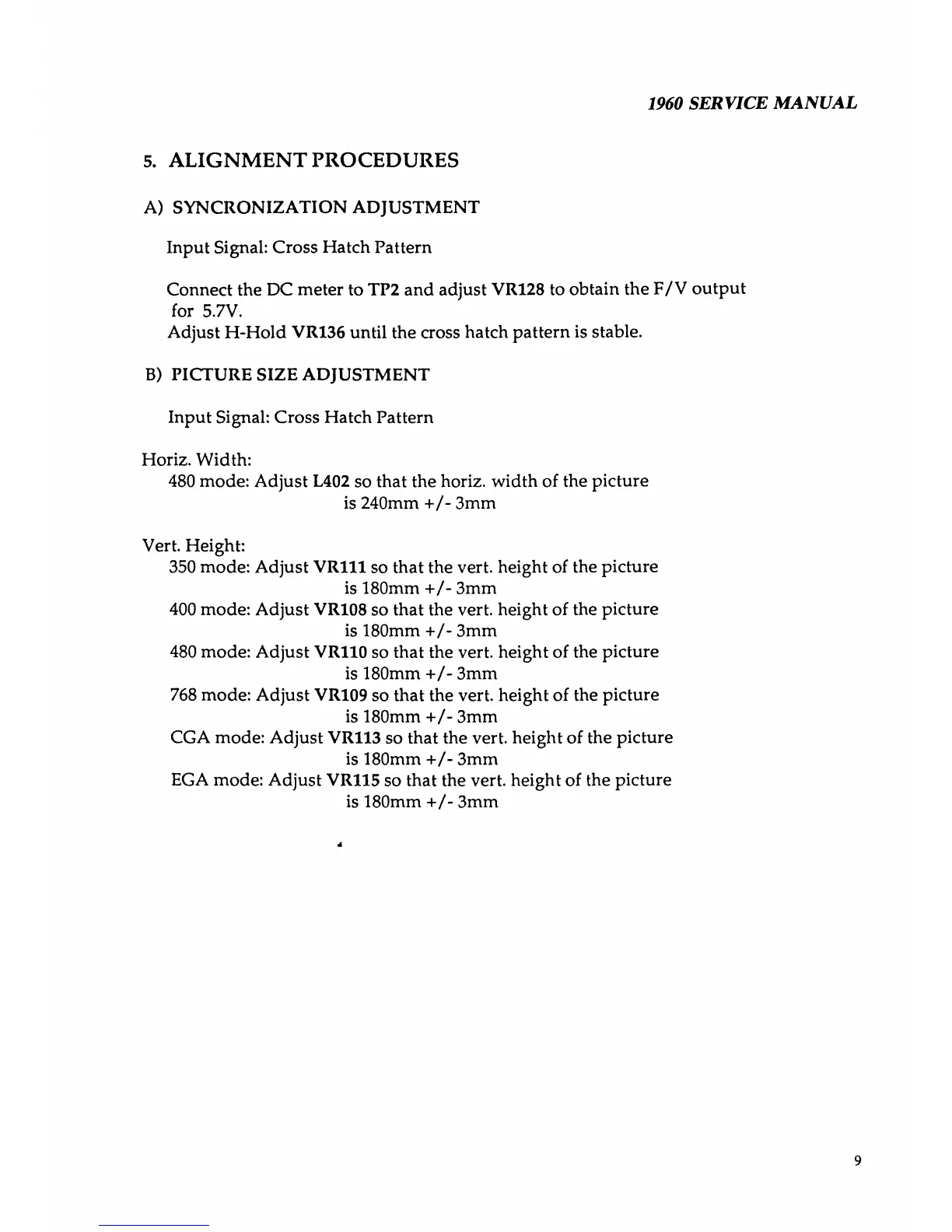
5. ALIGNMENT PROCEDURES
A) S YN CRON IZ ATI ON ADJUSTMENT
Input Signal: Cross Hatch Pattern
Connect the DC meter to TP2 and adjust VR128 to obtain the F/V output
for 5.7V.
Adjust H-Hold VR136 until the cross hatch pattern is stable.
B) PICTURE SIZE ADJUSTMENT
Input Signal: Cross Hatch Pattern
Horiz. Width:
480 mode: Adjust L402 so that the horiz. width of the picture
is 240mm +/- 3mm
Vert. Height:
350 mode: Adjust VR111 so that the vert, height of the picture
is 180mm +/- 3mm
400 mode: Adjust VR108 so that the vert, height of the picture
is 180mm +/- 3mm
480 mode: Adjust VR110 so that the vert, height of the picture
is 180mm +/- 3mm
768 mode: Adjust VR109 so that the vert, height of the picture
is 180mm +/- 3mm
CGA mode: Adjust VR113 so that the vert, height of the picture
is 180mm +/- 3mm
EGA mode: Adjust VR115 so that the vert, height of the picture
is 180mm +/- 3mm
4
9