Do you have a question about the Commodore 1701 and is the answer not in the manual?
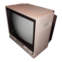
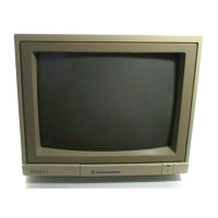
Overview of the C1701/C1702 monitors' quality and capabilities.
Specifies the 13-inch screen size and NTSC color standard.
Details the display resolution as 40 Columns x 25 lines.
Specifies the screen resolution as 1000 Characters per screen.
Lists the available user controls: Color, tint, brightness, contrast, volume, etc.
Notes the presence of a built-in audio amplifier and speaker.
Lists the supported inputs: Chrominance, luminance, composite video, and audio.
Highlights compatibility with video cassette recorders (1Vp-p, 75 Ohms).
Lists compatible Commodore computers: C64, VIC 20, Plus/4, C16.
Specifies power needs: 120 Volts, 60 Hz, 0.85 Amps.
States the power consumption as 87 Watts.
Safety rules for operation, maintenance, and replacement parts.
Procedures for dielectric strength and leakage current testing.
Information on the precision in-line gun type picture tube.
Procedure for adjusting color purity and vertical centering.
Adjusting static and dynamic convergence for image alignment.
Procedure for adjusting black & white tracking.
Adjustments for B1 voltage, focus, vertical position, and horizontal.
Adjustments for sub tint, color, sync, and 3.58 MHz trap.
High-level overview of monitor circuits and signal flow.
Detailed schematic of the video signal path.
Schematic of the audio amplification and output stages.
Schematic for decoding color signals.
Schematic for the color signal output to CRT.
Schematic for user controls and signal processing.
Schematic for horizontal and vertical oscillators and output.
Schematic for the horizontal output stage and flyback.
Lists symptoms for various component failures.
Troubleshooting steps for no picture/sound with normal B1 voltage.
Troubleshooting steps for no picture/sound with abnormal B1 voltage.
Troubleshooting for missing picture but present sound.
Troubleshooting for missing sound but present picture.
Troubleshooting for a single horizontal line display.
Troubleshooting for synchronization issues.
List of mechanical and electronic components for the 1701 chassis.
List of cabinet components for the 1701 model.
Parts for the main board of the 1701.
Parts for the CRT socket board of the 1701.
Parts for control and fuse boards of the 1701.
List of mechanical and electronic components for the 1702 chassis.
List of cabinet components for the 1702 model.
Parts for the main board of the 1702.
Parts for the CRT socket board of the 1702.
Parts for the regulator board of the 1702.
Specific parts for the 1702T model variant.
Parts for GE-1005A assemblies of the 1702.
Physical layout diagram of the 1701 main board components.
Physical layout diagram of the 1702 main board components.
Physical layout diagram of the 1702T main board components.
Explanations for 1701 schematic symbols and readings.
Explanations for 1702 schematic symbols and readings.
Notes on distinguishing 1702 model variants.
Form for registering the manual for updates.
| Display Type | CRT |
|---|---|
| Aspect Ratio | 4:3 |
| Audio Input | Yes |
| Audio Output | Yes |
| Refresh Rate | 60 Hz |
| Screen Size | 13 inches |
| Resolution | 640 x 200 |
| Compatibility | Commodore 64 |
| Power Supply | 120V AC, 60Hz |
| Weight | 22 lbs |