Interrupt
Mask
Register
(W)
(1FFF9
/
7FFF9)
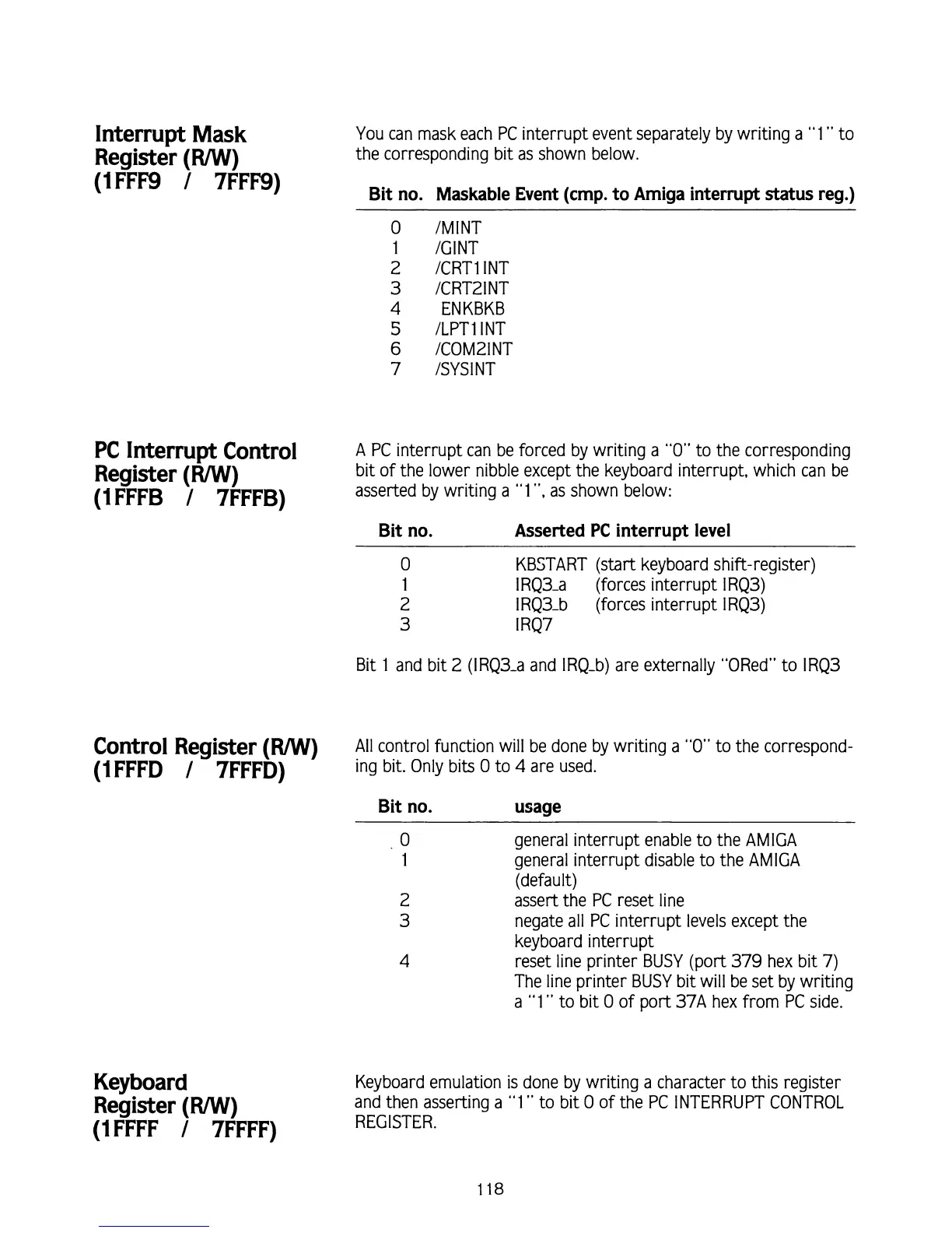
You can mask each PC interrupt event separately by writing a
"1
"
to
the corresponding bit as shown below.
Bit no. Maskable Event (cmp. to Amiga interrupt status reg.)
0
/MINT
1
/GINT
2
/CRT1 INT
3
ICRT21NT
4
ENKBKB
5
/LPTlINT
6
/COM21NT
7
ISYSINT
PC
Interrupt Control
A
PC interrupt can be forced by writing a
"0"
to the corresponding
Register
(W)
bit of the lower nibble except the keyboard interrupt, which can be
(IFFFB
/
7FFFB)
asserted by writing a
"1
",
as shown below:
Bit no. Asserted
PC
interrupt level
0
KBSTART (start keyboard shift-register)
1
I
RQ3-a (forces interrupt IRQ3)
2
I
RQ3-b (forces interrupt IRQ3)
3
I
RQ7
Bit
1 and bit 2 (IRQ3-a and IRQ-b) are externally "ORed" to IRQ3
Control Register
(W)
All
control function will be done by writing a
"0"
to the correspond-
(IFFFD
/
7FFFD)
ing bit. Only bits
0
to
4
are used.
Bit no. usage
Keyboard
Register
(W)
(IFFFF
/
7FFFF)
0
general interrupt enable to the AMlGA
1
general interrupt disable to the AMlGA
(default)
2
assert the PC reset line
3
negate all PC interrupt levels except the
keyboard interrupt
4
reset line printer BUSY (port
379
hex bit
7)
The line printer BUSY bit will be set by writing
a
"1" to bit
0
of port 37A hex from PC side.
Keyboard emulation is done by writing a character to this register
and then asserting a
"1"
to bit
0
of the PC INTERRUPT CONTROL
REGISTER.