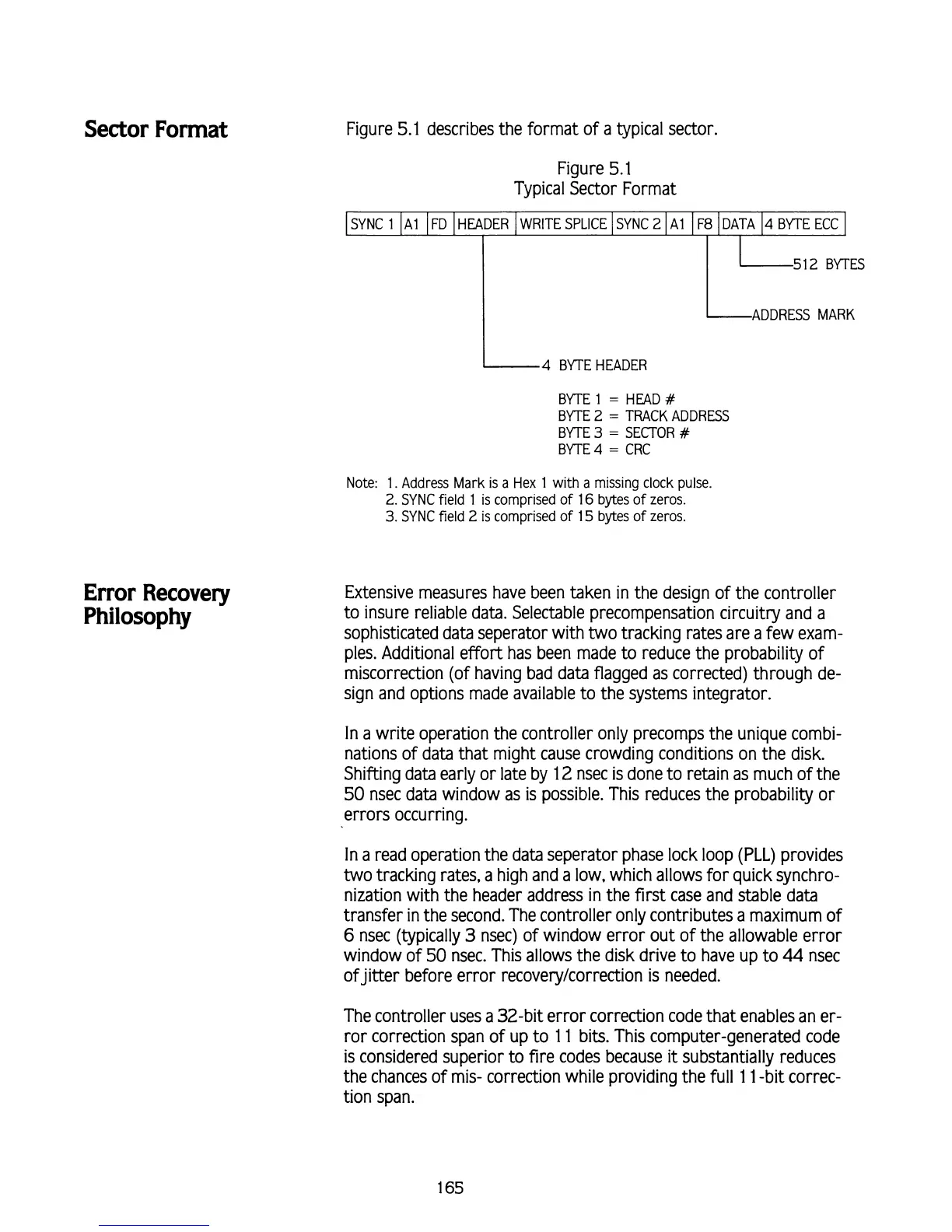
Sector Format
Figure 5.1 describes the format of a typical sector
Error Recovery
Philosophy
Figure 5.1
Typical Sector Format
SYNC
1
I
~l
I
FD
I
HEADER
I
WRITE SPLICE
I
SYNC
2
I
A1
I
F8
1
DATA
14
BYTE ECC
512
BYTES
-4
BYTE HEADER
BYTE
1
=
HEAD
#
BYTE
2
=
TRACK ADDRESS
BYTE
3
=
SECTOR
#
BflE
4
=
CRC
Note: 1. Address Mark is a Hex 1 with
a
missing clock pulse.
2.
SYNC field
l
is comprised of 16 bytes of zeros.
3.
SYNC field
2
is comprised of 15 bytes of zeros.
Extensive measures have been taken in the design of the controller
to insure reliable data. Selectable precompensation circuitry and a
sophisticated data seperator with two tracking rates are a few exam-
ples. Additional effort has been made to reduce the probability of
miscorrection (of having bad data flagged as corrected) through de-
sign and options made available to the systems integrator.
In a write operation the controller only precomps the unique combi-
nations of data that might cause crowding conditions on the disk.
Shifting data early or late by 12 nsec is done to retain as much of the
50 nsec data window as is possible. This reduces the probability or
errors occurring.
In a read operation the data seperator phase lock loop (PLL) provides
two tracking rates, a high and a low, which allows for quick synchro-
nization with the header address in the first case and stable data
transfer in the second. The controller only contributes a maximum of
6
nsec (typically
3
nsec) of window error out of the allowable error
window of
50
nsec. This allows the disk drive to have up to
44
nsec
ofjitter before error recoverylcorredion is needed.
The controller uses a 32-bit error correction code that enables an er-
ror correction span of up to 1 1 bits. This computer-generated code
is considered superior to fire codes because
it
substantially reduces
the chances of mis- correction while providing the full 1 l -bit correc-
tion span.