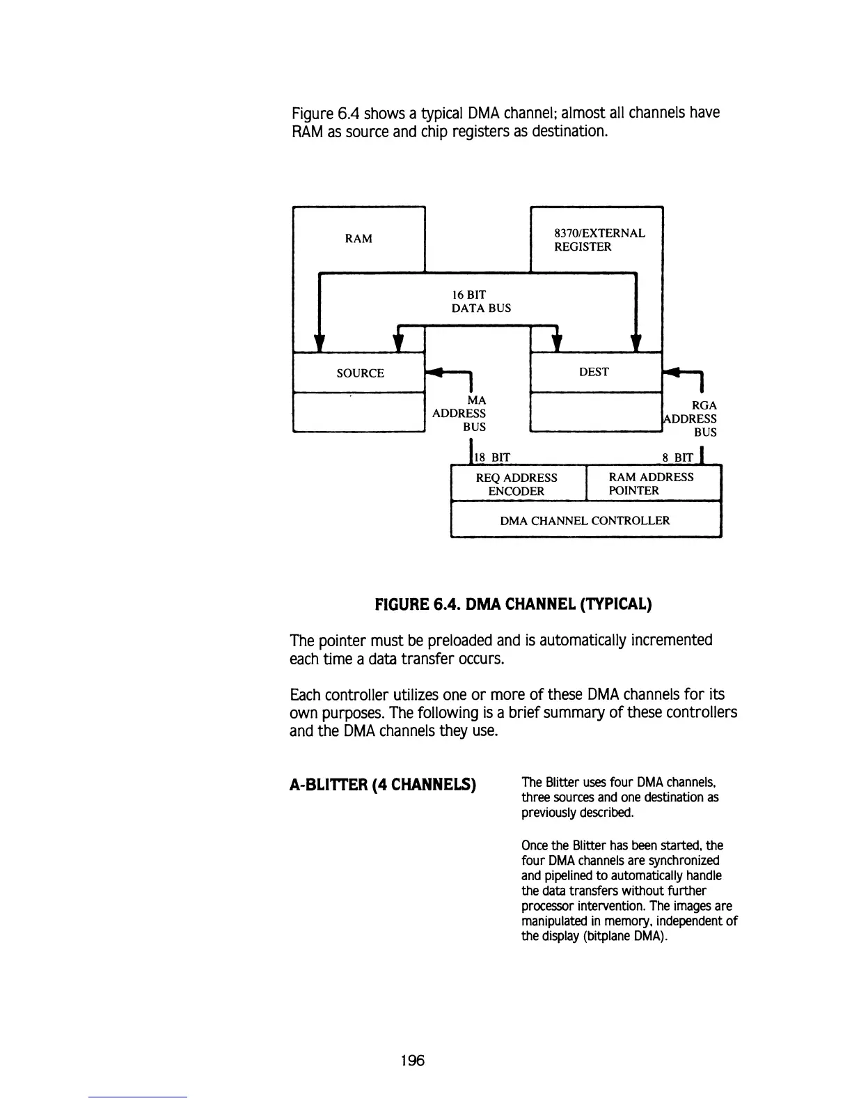
Figure
6.4
shows a typical
DMA
channel; almost all channels have
RAM
as source and chip registers as destination.
I
DMA CHANNEL CONTROLLER
I
FIGURE
6.4.
DMA
CHANNEL (TYPICAL)
The pointer must be preloaded and is automatically incremented
each time a data transfer occurs.
Each controller utilizes one or more of these
DMA
channels for
its
own purposes. The following is a brief summary of these controllers
and the
DMA
channels they use.
A-BLI'lTER
(4
CHANNELS)
The Blitter uses four
DMA
channels.
three sources and one destination as
previously described.
Once the Blitter has been started, the
four
DMA
channels are synchronized
and pipelined to automatically handle
the data
transfers without further
processor intervention. The images are
manipulated in memory, independent of
the display (bitplane
DMA).