Control
Registers
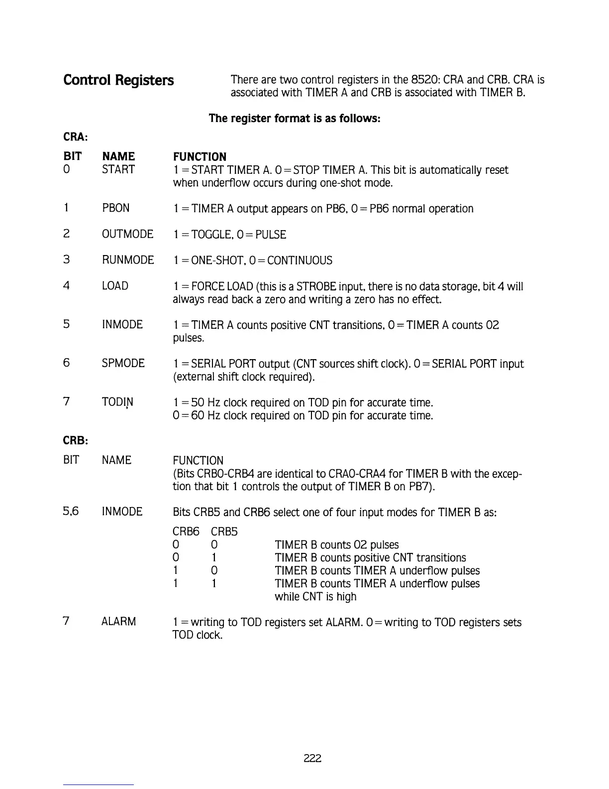
There are two control registers in the 8520: CRA and CRB. CRA is
associated with TlMER
A
and CRB is associated with TlMER B.
The register format is as follows:
CRA:
BIT
0
CRB:
BIT
NAME
START
PBON
OUTMODE
RUNMODE
LOAD
SPMODE
NAME
ALARM
FUNCTION
1
=START TlMER A.
0
=STOP TIMER A. This bit
is
automatically reset
when underflow occurs during one-shot mode.
1
=TIMER A output appears on PB6,O
=
PB6 normal operation
1
=TOGGLE,
0
=
PULSE
1
=
ONE-SHOT.
0
=
CONTINUOUS
1
=
FORCE LOAD (this is a STROBE input, there is no data storage, bit
4
will
always read back a zero and writing a zero has no effect.
1
=TIMER
A
counts positive CNT transitions,
0
=TIMER A counts
02
pulses.
1
=
SERIAL PORT output (CNT sources shift clock).
0
=
SERIAL PORT input
(external shift clock required).
1
=
50
Hz clock required on TOD pin for accurate time.
0
=
60
Hz clock required on TOD pin for accurate time.
FUNCTION
(Bits
CRBO-CRB4 are identical to CRAO-CRA4 for TlMER B with the excep-
tion that bit
1
controls the output of TlMER
B
on PB7).
Bits CRBS and CRB6 select one of four input modes for TlMER B as:
CRB6 CRBS
0
0
TIMER B counts
02
pulses
0
1
TIMER B counts positive CNT transitions
1
0
TIMER
B
counts TIMER A underflow pulses
1 1
TIMER
B
counts TIMER A underflow pulses
while CNT is high
1
=writing to TOD registers set ALARM.
0
=writing to TOD registers sets
TOD clock.