BACKPLANE TIMING
Clock
Buffers
GENERATION
Generating 7M
DOE, ASDELAYED*,
ASQSO*
The clock buffers for C1
*,
C3*, and CDAC were chosen for minimum
propagation delay and minimum skew. Notice that buffered clocks
are passed to the 100 pin edge connectors, but that the unbuffered
clocks are passed to the
86
pin connector that goes on to the next
box in order to minimize propagation delay to the next backplane.
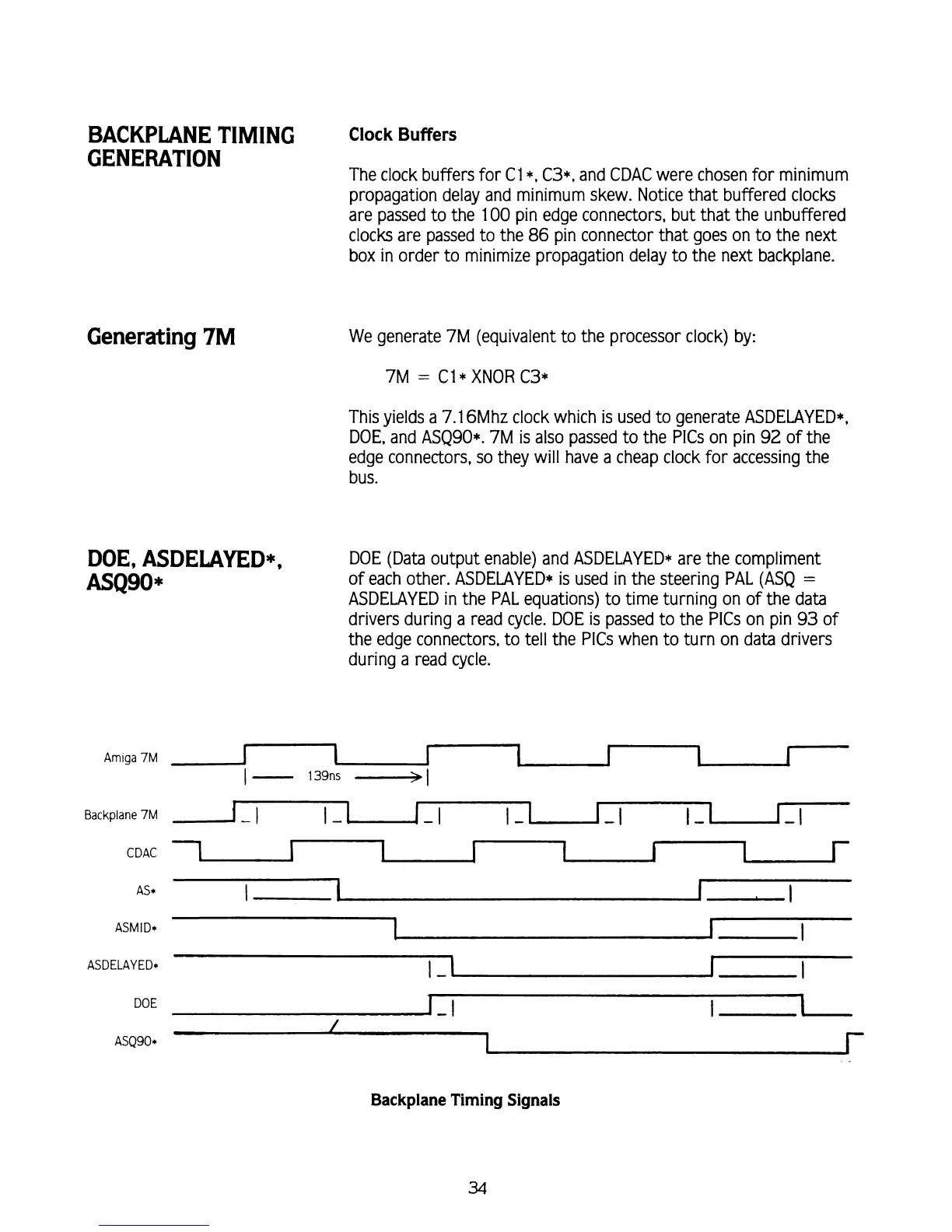
We generate 7M (equivalent to the processor clock) by:
7M
=
C1
*
XNOR C3*
This yields a 7.1
6Mhz clock which
is
used to generate ASDELAYED*,
DOE, and
ASQSO*. 7M is also passed to the PlCs on pin 92 of the
edge connectors, so they will have a cheap clock for accessing the
bus.
DOE (Data output enable) and ASDELAYED* are the compliment
of each other. ASDELAYED* is used in the steering PAL (ASQ
=
ASDELAYED in the PAL equations) to time turning on of the data
drivers during a read cycle. DOE
is
passed to the PlCs on pin
93
of
the edge connectors, to tell the PlCs when to turn on data drivers
during a read cycle.
Backplane
7M
1-1
1-1
1-1
1
-I
CDAC
1
1
1
I
I
AS*
l
1
I
I
ASDELAYED*
F
I
I
Backplane Timing Signals
34