ZOO0
SYSTEM
BUS
LOADING
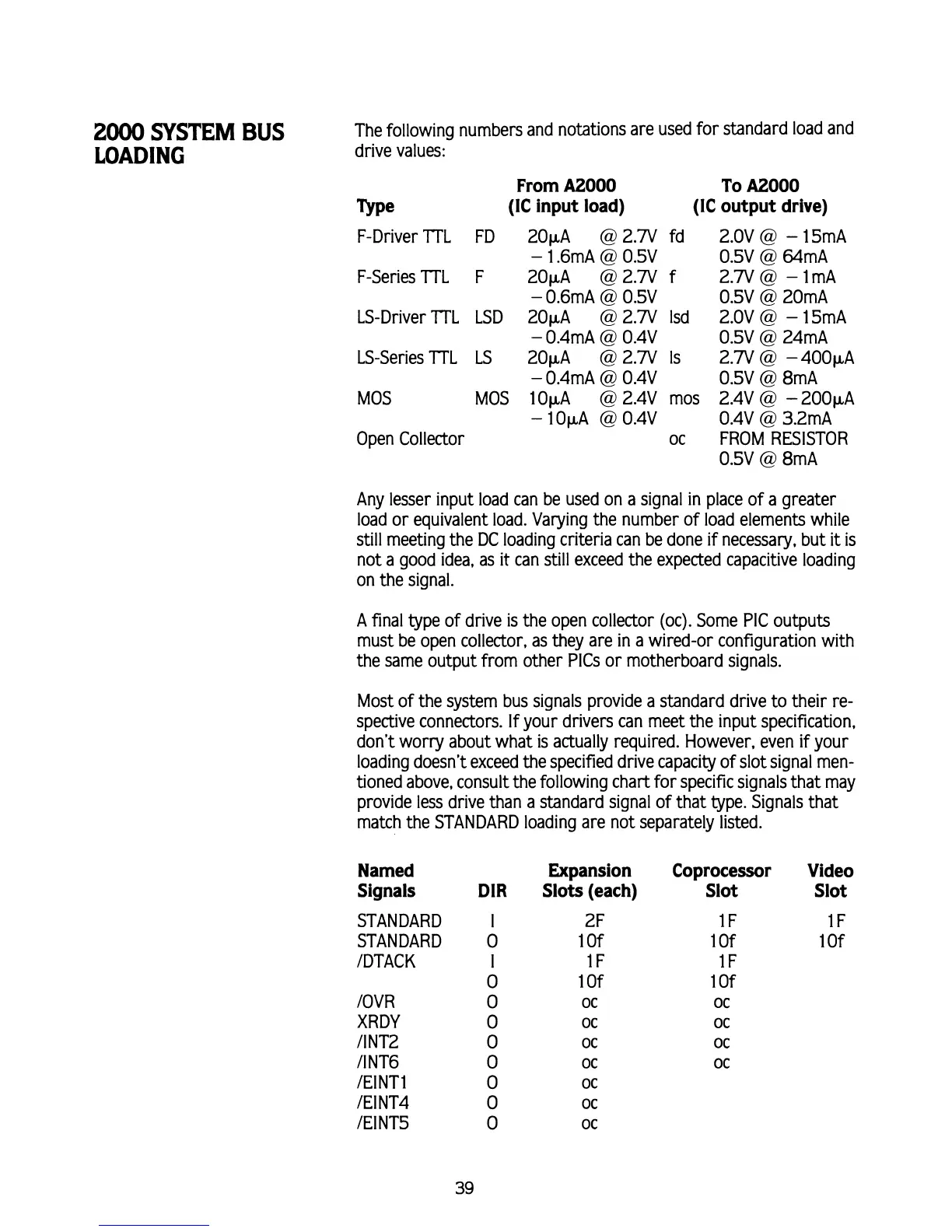
The following numbers and notations are used for standard load and
drive values:
From
A2000
To
A2000
we
(IC input load) (IC output drive)
F-Driver
IT1
FD 20pA
@
2.W fd
-
1.6mA
@
O.5V
F-Series
IT1
F 20pA
@
2.W f
-
0.6mA
@
0.5V
LS-Driver
ITL
LSD 20pA
@
2.W Isd
-
0.4mA
@
0.4V
LS-Series 7TL LS 20pA
@
2.W Is
-
0.4mA
@
0.4V
MOS MOS lOpA
@
2.4V
~OS
-
lOpA
@
0.4V
Open Collector oc
2.OV
@
-
15mA
0.5V
@
64mA
2.W@ -1mA
0.5V
@
20mA
2.OV
@
-
15mA
0.5V
@
24mA
2.W
@
-400p.A
0.5V
@
8mA
2.4V
@
-
200pA
0.4V
@
3.2mA
FROM RESISTOR
0.5V
@
8mA
Any lesser input load can be used on a signal
in
place of a greater
load or equivalent load. Varying the number of load elements while
still meeting the DC loading criteria can be done if necessary, but
it
is
not a good idea, as it can still exceed the expected capacitive loading
on the signal.
A
final type of drive is the open collector (oc). Some PIC outputs
must be open collector, as they are in a wired-or configuration with
the same output from other
PlCs or motherboard signals.
Most of the system bus signals provide a standard drive to their re-
spective connectors. If your drivers can meet the input specification,
don't worry about what is actually required. However, even if your
loading doesn't exceed the specified drive capacity of slot signal men-
tioned above, consult the following chart for specific signals that may
provide less drive than a standard signal of that type. Signals that
match the STANDARD loading are not separately listed.
Named
Signals
STANDARD
STANDARD
IDTACK
IOVR
XRDY
ANT2
ANT6
IEINT1
/El NT4
IEINT5
DIR
Expansion
Slots (each)
2
F
1 Of
l F
1
Of
OC
OC
OC
OC
OC
OC
OC
Coprocessor Video
Slot Slot