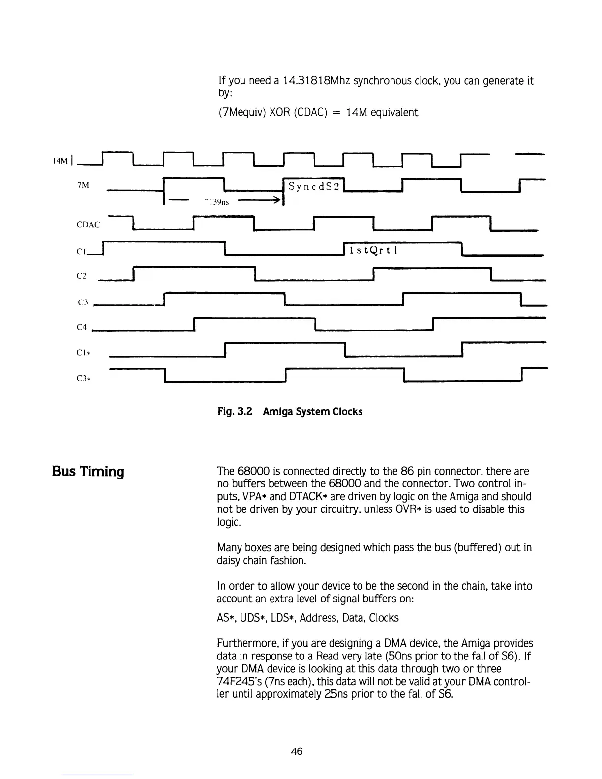
If
you need a 14.31 81 8Mhz synchronous clock, you can generate
it
by
:
(7Mequiv)
XOR
(CDAC)
=
14M equivalent
CDAC
I
1
1
l
I
I
C
I
1
rlstertl
C?.
Fig.
3.2
Amiga
System
Clocks
Bus
Timing
The
68000
is connected directly to the
86
pin connector, there are
no buffers between the
68000
and the connector. Two control in-
puts, VPA* and DTACK* are driven by logic on the Amiga and should
not be driven by your circuitry, unless OVR*
is
used to disable this
logic.
Many boxes are being designed which pass the bus (buffered) out in
daisy chain fashion.
In order to allow your device to be the second in the chain, take into
account an extra level of signal buffers on:
AS*, UDS*, LDS*, Address, Data, Clocks
Furthermore, if you are designing a DMA device, the Amiga provides
data in response to a Read very late
(50ns prior to the fall of S6). If
your DMA device is looking at this data through two or three
74F245's (7ns each),
this
data will not be valid at your DMA control-
ler until approximately
25ns prior to the fall of S6.