Viewed looking straight on into socket. RJ11 connector. Female.
1 +5V DC
2 (I)/ O Keyboard clock
3 I / O Keyboard data
4 Ground
Usual stuff: I'm not responsible for blowing up Ami, etc; use at own risk, etc, etc. Having said this, it did
work for me. :) Ref's used: Amiga Hardware Reference Manual (A1000) & the good ol' CD32-FAQ.
Taken from an Email by Chris Naylor.
CD32 power port
View straight on. 4 pin din.
1 +5V
2 +12V
3 Ground
4 Unknown
Put a ground jumper from pin 3 to the shield. You can modify another Amiga power supply (eg. A500)
for this by replacing the connector at the end of the lead.
Taken from a posting by Michael Litchfield.
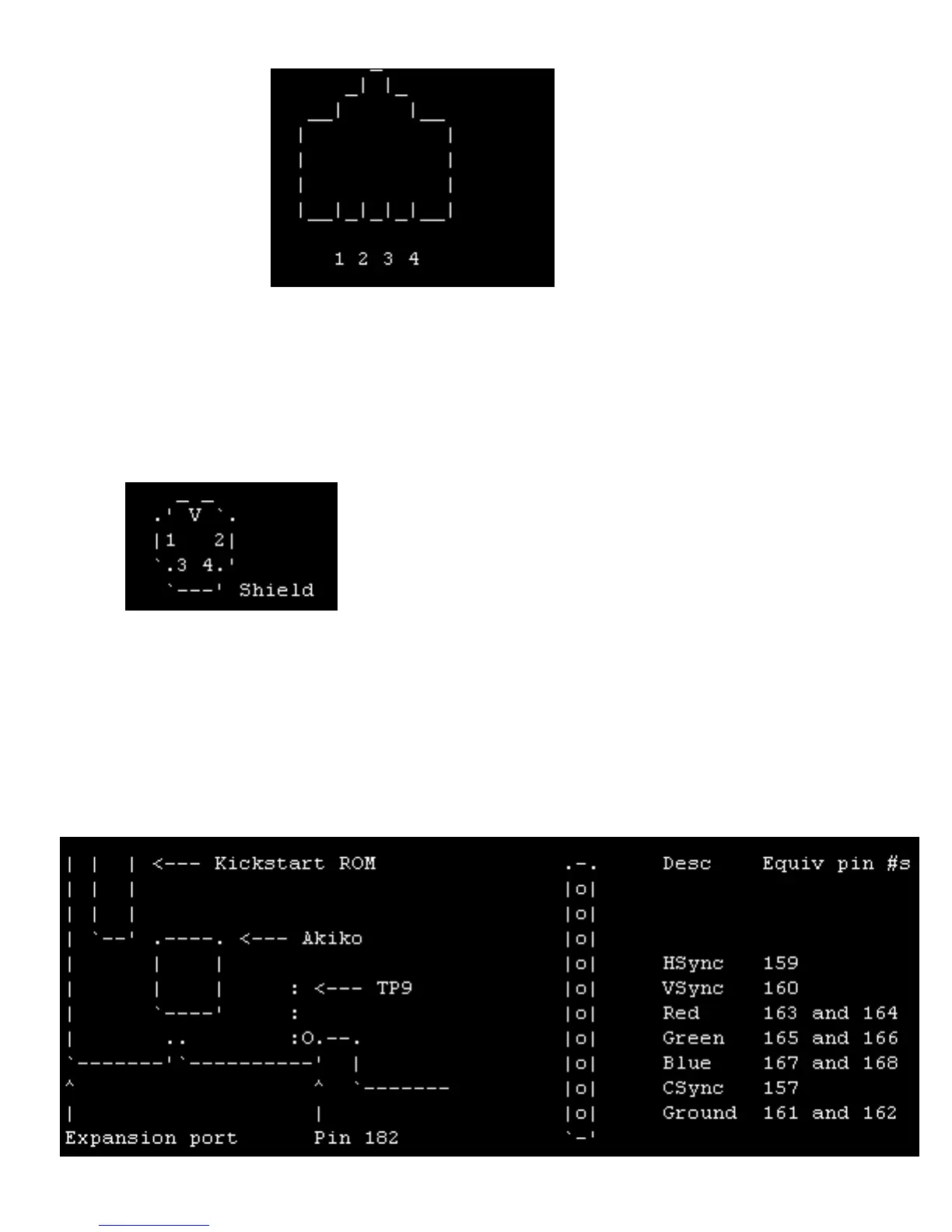
CD32 RGB
The RGB signals are available from a test port, TP9...
file:///C|/sites/amigaemulation/cd32/CD32FAQ/CD32_FAQ_2000.htm (37 of 39) [3/9/2000 1:55:14 PM]