This document outlines the installation procedures for the COMMSCOPE CMAX-OUS1-UW-I53 and CMAX-OUS1-UW43-I53 antenna models, providing two distinct methods for mounting these devices. These antennas are designed for ceiling installation, offering discreet integration into various environments.
Function Description:
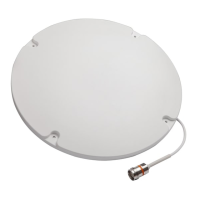
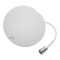
The CMAX-OUS1-UW-I53 and CMAX-OUS1-UW43-I53 are ceiling-mounted antennas, primarily designed to extend wireless coverage within indoor spaces. They feature a compact design that allows for flush or semi-flush mounting, making them suitable for environments where aesthetics and minimal visual impact are important. The antennas are equipped with pigtails for connection to external equipment, facilitating signal transmission and reception. Their installation methods cater to different ceiling types and preferences, ensuring versatility in deployment.
Important Technical Specifications:
Method 1 (Flush Mount):
- Size of Installation Hole: A circular hole with a diameter of 28mm (0.7in) is required in the ceiling tile.
- Ceiling Thickness (T): This method is suitable for ceiling tiles with a thickness of less than 15mm (0.59in).
- Lock Nut: The antenna utilizes a lock nut with a diameter of 49mm and a thickness of 13mm for secure fastening.
- Antenna Dimensions (Approximate): The circular antenna body has an approximate diameter of 208mm (±0.2mm).
Method 2 (Screw Mount):
- Size of Installation Hole: A circular hole with a diameter of 28mm (0.7in) is required for the antenna's pigtails.
- Expansion Nail Hole Size: Three holes with a diameter of 6mm (0.24in) are needed for the plastic expansion nails.
- Plastic Expansion Nails: The recommended size for the plastic expansion nails is 6*27.
- Self-Tapping Screws: The recommended size for the self-tapping screws is 4*25.
- Antenna Dimensions (Approximate): The circular antenna body has an approximate diameter of 208mm (±0.2mm).
General Specifications:
- Cable Minimum Bending Radius: The antenna cables require a minimum bending radius of 40mm to prevent damage and ensure optimal performance.
Usage Features:
Method 1 Installation (For thinner ceilings):
- Hole Preparation: A 28mm diameter hole is cut into the ceiling tile.
- Nut Removal: The retaining nut is removed from the back of the antenna.
- Pigtail Feeding: The two pigtails of the antenna are fed through the prepared hole in the ceiling tile.
- Nut Re-installation: The retaining nut is re-installed and tightened to securely fasten the antenna to the ceiling tile, ensuring a close-fitting attachment. This method provides a clean, flush-mount appearance.
Method 2 Installation (For more robust attachment or different ceiling types):
- Hole Positioning and Drilling: The antenna is positioned, and three screw holes are marked and drilled according to the specified size (6mm diameter).
- Expansion Pin Insertion: Plastic expansion pins (6*27) are inserted into the drilled holes.
- Pigtail Feeding: The two pigtails of the antenna are fed through the 28mm diameter hole in the ceiling tile.
- Antenna Securing: Self-tapping screws (4*25) are used to lock the antenna to the ceiling, aligning with the corresponding hole positions. This method provides a more robust attachment.
- Optional Screw Hole Cover: Screw hole covers are available as optional accessories to conceal the screw heads, enhancing the aesthetic finish.
Both methods emphasize feeding the antenna's pigtails through the ceiling, indicating that the primary connection points are located on the back of the antenna, hidden from view once installed. The circular design of the antenna (approximately 208mm in diameter) contributes to its unobtrusive profile.
Maintenance Features:
The document does not explicitly detail maintenance features. However, the design suggests that the antennas are largely maintenance-free once installed. The robust installation methods (especially Method 2 with screws) imply a secure and long-lasting fixture. The availability of screw hole covers in Method 2 suggests a consideration for long-term aesthetics and protection of the screw heads. The specified cable minimum bending radius is a critical factor during installation to prevent damage to the internal wiring, which could otherwise lead to performance degradation and necessitate replacement rather than simple maintenance. In case of issues, the technical support link provided (http://www.commscope.com/wisupport) would be the primary resource for troubleshooting and potential service. The "Note" regarding cable bending radius is a preventative measure, ensuring proper installation to avoid future performance issues.