M0153A8A_InstI nstr _CMA X-OUS1-UWxx-i53
http://www.commscope.com /wisu pp or
Installation Steps
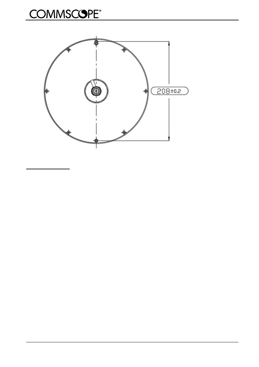
1) Position and drill three screw holes of specified size.
2) Put plastic expansion pins in the holes first.
3) Feed these two pigtails of this antenna through th e hole in the ceiling tile.
4) Use 4*25 self-tapping screws to lock the antenna to the ceiling according to the
corresponding hole position.
5) Then cover the screw hole cover (available, but not required).
Note:
Cable min. bending radius: 40mm
© Copyrig ht 2020 Com m Scope, Inc.
All r ig hts r eser ved.
All inform ation contained in this m anual has been r evised thoroug hly. Yet C om m Scope accepts no li abili ty for any omissi ons or
faults.
Com m Scope reser ves the right to chang e all har dware and software characteristics without notice.
Nam es of products mentioned herein ar e used for identification purposes only and may be trademarks and / or reg istered
trademarks of their respective companies.
No par ts of this publication may be reproduced, stored in a retr ieval system , transmitted in any form or by any means, electronical,
mechanical photocopying , r ecor ding or other wise, without pr ior written permission of the publisher .
Com m Scope, 18-M ay-2020