Distributed Design Series - DP6 / DP8 Installation Guide Page 3
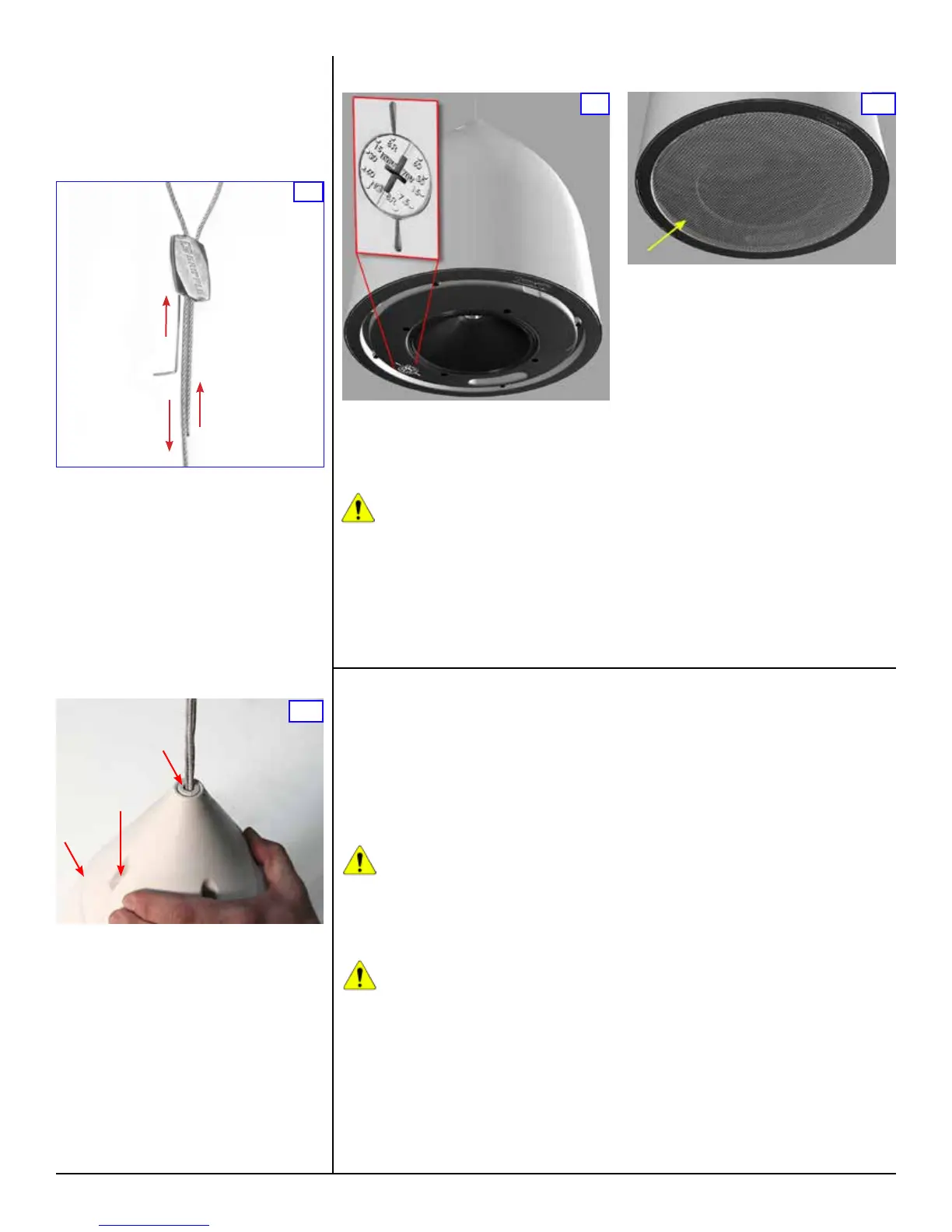
To gain access to the tap switch (inset above),
remove the loudspeaker grille by lifting the
strapping tape attached on either side of the
grille. Once the grille is off, remove the tape and
set the tap switch to the appropriate tap setting.
CAUTION: Do NOT change the setting
on the tap switch while the loudspeaker
is in use. Turn off the power amplier
before adjusting this switch.
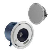
The tap switch is located on the front bafe
adjacent to the loudspeaker cone (red arrows
and inset in Figure 9, yellow arrow in Figure 10).
You can use a standard #2 or #3 Phillips or a
medium slot-blade screwdriver (not the one
provided with the loudspeaker kit), or just press
9
Loudspeaker Tap Setting
with your thumb rmly, and twist to adjust
the power control dial on the front face of the
loudspeaker bafe. As shown in Figure 9, you
can make any of ve different settings, although
the dial has dual calibrations so at rst glance
it appears to have ten settings. The 8-ohm
position is the same on both sides and is for a
low impedance connection. On the lower-left side
of the power tap control shown in the close-up
on Figure 8 are the power values for 100-volt
connections, and on the upper right side are the
power values for 70-volt connections.
Note: The letters NC mean “no-connect” but they
do not actually break a connection. DO NOT USE
this setting if you’re using a 100-volt distribution
scheme as the loudspeaker may draw excessive
power; it corresponds to the highest power that
can be drawn with a 70-volt source.
This control makes it very easy and fast to
balance an installation since there is no need
to open the loudspeakers and move wires to
different terminals. Just be sure there is no
applied signal when you are actually changing
the tap switch setting. When the desired setting
is conrmed, replace the grille.
10
Note: It is best to begin with the loudspeaker
lower than the anticipated nal height, and lift
it into position. It can be lowered later by using
the Gripple Setting Key, as shown in Figure 7,
but best practice is to set the height primarily by
raising the unit.
For extra weatherproong, apply a small bead
of silicon sealant around the ridge on the
loudspeaker body where the top will join it (Figure
8A). Slide the loudspeaker cover into position
so its four recessed holes align with the four
threaded ttings on the top of the loudspeaker
(Figure 8B). Then insert the four provided
machine screws and fasten the cover. Finally,
press the split cover plug into place (Figure 8C).
Also apply some silicon sealant on the inside and
outside surfaces of the split cover plug before
installing.
If you have purchased the optional PST-14
Decorative Plastic Tubing, this is an appropriate
time to install it.
8
C
A
B
To lower a loudspeaker which is already clamped
by the Gripple, refer to Figure 7.
A. Insert the setting key into the small hole in the
bottom of the Gripple, which forces the internal
locking wedges open, and then,
B. Slide the cables to lower the loudspeaker.
Use this method rst to create some extra slack
in the safety cable, then support the loudspeaker
with your hand as you pull the main support
cable, lowering the loudspeaker to the desired
height. Finally remove the setting key to lock the
loudspeaker in place, and re-tension the safety
cable by pulling the loose end until it is snug.
7
A
B
Painting the Loudspeaker
These loudspeakers are easy to paint. It’s best to
paint the bafe and enclosure before installation.
Type of Paint
The loudspeaker’s ABS plastic bafe and
enclosure accept almost any type of latex
or oil-based paint. A two-coat application is
recommended.
Caution: When applying paint or other
coating, ensure that a dedicated
Gripple decor cover is used to cover
the Gripple. This will ensure that the movement
of the locking wedges inside the assembly is
not impaired. After painting, the Gripple
should not be repositioned on the cable.
Caution: Use only light mineral
spirits thinner as a cleaner. NEVER
use gasoline, kerosene, acetone,
methyl ethyl ketone (MEK), paint thinner,
harsh detergents or other chemicals as they
may permanently damage the loudspeaker.
Some of these chemicals are also toxic and
highly ammable.
Painting Process
To obtain the best results follow this procedure:
1. Clean the bafe and enclosure with a light
solvent such as mineral spirits, rubbing with a
lightly dampened cloth. Do not use abrasives
such as sandpaper or steel wool.
2. Mask the loudspeaker so that the surround,
cone and center area will not receive any paint.
Use a low-tack painter’s tape (typically blue
in color) to avoid damaging the loudspeaker
surround when the tape is removed. We advise
against using conventional masking tape and
NEVER use duct tape in this application; these
kinds of tape generally leave adhesive residue
that can be difcult to remove and that may
actually cause damage.
After cleaning, apply two or more two thin coats
of either latex or oil-based paints. Latex paint will
adhere better if an oil-based primer is used rst.
Apply the paint with a roller or brush, or spray
it on.
The grille should be painted separately, and when
it is not in place on the loudspeaker. We further
recommend that you remove the grille’s internal
cloth mesh, then spray paint the grille assembly.
Avoid using a roller or brush to paint the grille as
its metal perforated holes may become clogged
with paint, which degrades sound quality and
also may attenuate the sound. Reinstall the
internal cloth mesh (or if damaged install a new
cloth mesh).
 Loading...