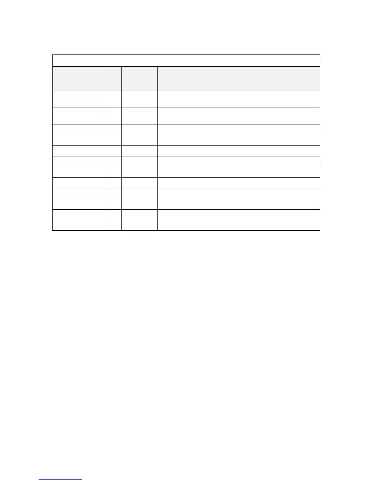
DC/DC Interface
DC/DC
Signals I/O
Voltage
Level
Description
EC_ON# I 0~floating Active Low, NS87591 use this pin to control the system
power on/off.
ACOFF I 0~3.3V Active High, turn off the adaptor power for battery automatic
learning cycle.
ACIN O 0~3.3V Active High, go high when adaptor plug-in.
VGATE O 0~3.3V Active High, go high when +CPU_CORE ready.
VR_ON I 0~3.3V Active High, turn on/off the +CPU_CORE, +1.2VP
VID[0..4] I 0~3.3V CPU VID
FSTCHG I 0~3.3V Active High, NS87591 use this pin to enable charger.
IREF I 0~3.3V NS87591 DAC output, it control the charging current.
SMB_EC_CK1 I/O 0~5V SMBus Clock.
SMB_EC_DA1 I/O 0~5V SMBus data.
BATT_TEMP O 0~3.3V Battery Temperature detect pin
SUSP# O 0~3.3V Active High, NS87591 use this pin to suspend system
BATTERY
Lithium-Ion battery for ACY25 series
18650 2P4S, 14.8V/3900mAH, Lithium-Ion battery
Built-in protection and gas gauge function.
More than 300 charging/discharging cycles.
Modularized battery pack, easy to be replaced.
On board RTC battery: Maxell ML1220/1FC 3V/14mAH Lithium or
Sanyo ML1220-TT28 3V/15mAH Lithium
Chapter 4-6