Do you have a question about the Compal JHL90 and is the answer not in the manual?
Details specifications for the 2.5" Hard Disk Drive.
Lists types of optical disc drives supported.
Provides dimensional specifications for the touch pad.
Details dimensional specifications for the keyboard.
Lists specifications for the LCD display device options.
Lists specifications for the camera module.
Lists features of the keyboard.
Details specifications for Wireless LAN connectivity.
Details specifications for the internal modem.
Details specifications for Bluetooth connectivity.
Details specifications for the TV tuner card.
Lists specifications for optional accessory packs.
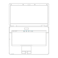
Describes the mechanical functions and features of the system.
Specifies the mechanical materials used in the notebook's construction.
Summarizes core hardware specifications like CPU, memory, storage, and display.
Details communication interfaces, input devices, and I/O ports.
Covers system features, security, power management, and software aspects.
Details the functionality of system power and lid control buttons.
Refers to system status indicators for monitoring.
Explains the functionality for selecting the boot sequence.
Describes the feature to display a custom OEM screen during boot.
Explains the boot block's role in BIOS recovery.
Introduces the ACPI power management mode.
Details how system time-outs are managed in ACPI mode.
Describes various system power states like G3, S0, S3, S4.
Details power management features for CPU, Hard Disk, and Display.
Explains the system hibernation feature and its saving mechanism.
Introduces the Advanced Configuration and Power Interface standard.
Lists supported ACPI sleep states (S3, S4, S5).
Details the time limits for resuming from ACPI sleep states.
Illustrates the state transition diagram for ACPI power management.
Discusses ACPI specification for reporting storage devices and batteries.
Details the system's capability to boot from various devices.
Describes the role of the embedded controller in ACPI.
Details the system's single BIOS ROM configuration.
Describes features related to USB support and bootability.
Explains the utility for programming system and keyboard BIOS.
Describes the system's crisis recovery feature using a Flash Disk.
Details VGA support and external monitor detection.
Explains how system type and BIOS version are displayed during boot.
Details automatic updates and management of CMOS RAM.
Describes System Management BIOS version and DMI data.
Details the EEPROM map and its data storage layout.
Describes the procedure to enter the system setup utility.
Details the various screens and options within the system setup utility.
Explains the purpose and lists features of the EC-FW.
Details the different types of EC-FW available.
Explains the system control functions assigned to hot keys.
Details external buttons, IOMP button functions, and related controls.
Explains the control mechanisms for adapter power loading.
Describes the status and control of external LEDs on the system.
Shows the block diagram for the JHL90/91 Series Power System.
Describes the performance and characteristics of the 90W AC adapter.
Lists the key features of the AC adapter.
Details the electrical specifications of the AC adapter.
Provides a description of the DC-DC converter's function.
Lists the key features of the DC-DC converter.
Details the electrical specifications of the DC-DC converter.
Specifies the operating and storage temperature ranges.
Details the battery charging mechanism and specifications.
Lists the over-current protection thresholds for various rails.
Lists the over-voltage protection thresholds for various rails.
Lists the under-voltage protection thresholds for various rails.
Describes the short circuit protection mode.
Details the DC-Jack and Battery Connector I/O interfaces.
Details Li-Ion battery specifications and connector pin assignments.
Lists the features of the LCD inverter.
Specifies the absolute maximum ratings for the inverter.
Details the electrical characteristics of the inverter.
Details the electrical specifications of the inverter.
Describes the input and output connectors for the inverter.
Outlines safety protection measures for the inverter.
Specifies the Mean Time Between Failures (MTBF).
Lists reference documents for further information.
Specifies performance criteria for Electro-Static Discharge.
Lists the power requirements for system voltage rails.
Defines the power and EE interface voltage rails.
Illustrates the power sequence diagrams for AC and suspend/resume.
Details the steps to remove the battery pack.
Details the steps to remove the HDD module.
Details the steps to remove the DDR RAM module.
Details the steps to disassemble the optical drive (ODD).
Details the steps to remove the keyboard.
Details the steps to remove the LCD module assembly.
Details the steps to remove the logic upper assembly.
Details the steps to remove the motherboard.
Checks power cord connections and power supply adequacy.
Checks for obvious shorts, opens, or damaged components.
Verifies OS installation, password, and optional equipment status.
Guides user through flowchart steps for diagnosing issues.
Checks battery and power LEDs for status.
Guides on replacing the adapter or battery.
Checks power supply connections and wiring.
Runs diagnostic tests for power supply issues.
Checks system board fuses and connections for replacement.
Checks display functionality using an external monitor.
Runs diagnostic tests for display issues.
Checks display component connections and performs replacements.
Checks keyboard functionality using an external keyboard.
Runs diagnostic tests for keyboard issues.
Checks keyboard connections and performs replacements.
Checks external USB device connections and functionality.
Replaces the system board if issues persist.
Checks CRT connection integrity and cable.
Checks CRT display set functionality.
Checks HDMI connection integrity and cable.
Checks HDMI display set functionality.
Checks touch pad connection and cable integrity.
Checks and replaces the touch pad unit if faulty.
Tests audio sources to identify sound issues.
Tests speaker functionality using earphones.
Checks speaker cable connection to the system board.
Checks and replaces stereo speakers if faulty.
Checks CD-ROM/DVD drive functionality with an audio CD.
Guides on cleaning the CD/DVD drive.
Verifies correct driver installation for the drive.
Runs diagnostic tests for the CD/DVD drive.
Checks drive connections and performs replacement.
Checks telephone line and modem port connections.
Checks modem card connection to the system board.
Checks and replaces modem card or RJ-11 jack.
Runs a test program for the express card.
Checks and replaces the express card socket.
Runs diagnostic tests for the wireless LAN system.
Checks wireless LAN connections and performs replacements.