JHL90 Service Manual
4.4 Electrical specification
4.4.1 Electrical specification
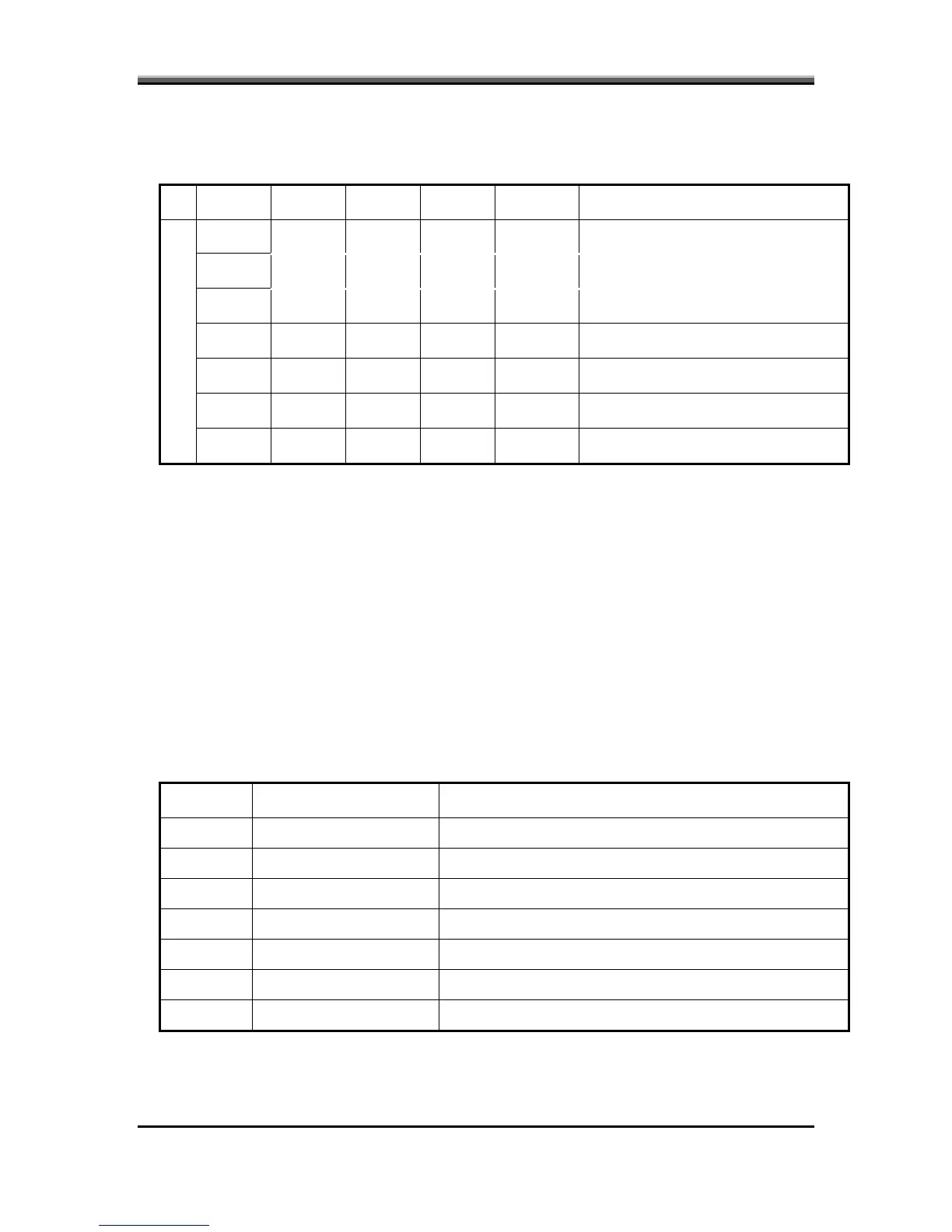
No Symbol Min. Typ. Max. Unit Comment
V
oper
. -- 650 -- Vrms Lamp operating voltage (650+/-50)
I
L
6.2 6.5 6.8 mArms DAC_BRIG: 0 V, PWM: 100%
I
L
3.0 3.3 3.6 mArms DAC_BRIG: 0 V, PWM:30%
I
L
5.7 6 6.3 mArms DAC_BRIG: 1 V, PWM: 100%
I
L
2.7 3 3.3 mArms DAC_BRIG: 1 V, PWM:30%
f 45 55 65 KHz
1
η
80% -- -- --
4.4.2 Thermal
All components on inverter board should follow below rules:
• Component using conditions (component stress) must be within component
specification including voltage rating, current rating, temperature etc.
• Component temperature should follow below:
Δ T < 30°C, at 25, 35°C.
Component temperature should be less than 70°C inside system at 35°C.
4.5 Connector description
4.5.1 Input Connector:
CN1: ACES 87213-0700; JST SM07B-SRSS-TB
Symbol Description
1 INV_PWR Input voltage (9V-21V)
2 INV_PWR Input voltage (9V-21V)
3 INV_PWM Adjust brightness by burst mode (3.3 V 150Hz)
4 DISOFF # Backlight on/off control, active HIGH (3.3V)
5 DAC_BRIG Max. current limit
6 GND Power system return
7 GND Power system return
4.5.2 Output Connector:
CN2: JST_SM02B_BHSS-1
4-15