MODEL 36, TYPE B & C
SINGLE RANGE TENSIONCELLS
INSTRUCTION MANUAL A-279
3
Copyright 2023 - Revised Comptrol All Rights Reserved
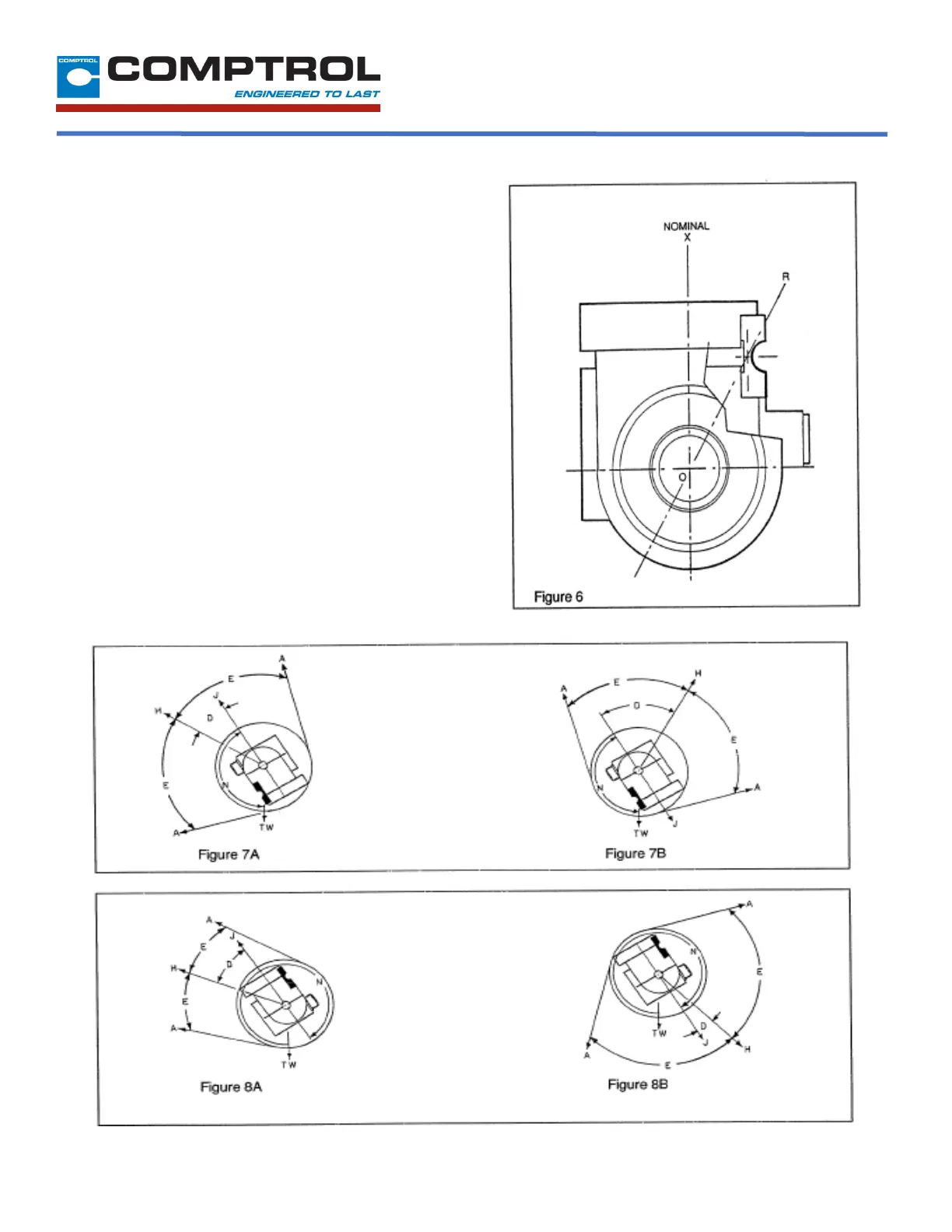
I-E DESCRIPTION OF OPERATION
The total resultant load per cell (JT) is calculated by
resolving web force vectors acting upon the
Tensioncells, with respect to the Loading Line (OX). (JT)
is the resultant of both TENSION and TARE loads, PER
CELL! (See Figure 6)
The intrinsic design of Comptrol Tensioncells allows the
location of the Resultant Load of Web Tension (H) on
any angle with respect to the Load Line (OX). Note,
however, that the Total Force vector (JT) must always
be calculated on the line (OX).
Any force vector falling on the line (OR) (through the
pivot point of the C-Flexure) will produce no deflection,
and thus no change in electrical output.
Rotating the Tensioncell on its mounting bolt changes
the force vectors on the cell. This feature makes it
possible to minimize the tare component and maximize
the load signal output.
The resultant tare is minimized by mounting the
Tensioncell so that (N) is 149° (See Figure 7A and 7B)
or so that (N) is 329° (See Figure 8A and 8B).
 Loading...