MODEL 36, TYPE B & C
SINGLE RANGE TENSIONCELLS
INSTRUCTION MANUAL A-279
4
Copyright 2023 - Revised Comptrol All Rights Reserved
PART II - INSTALLATION AND OPERATION
II-A INSPECTION UPON DELIVERY
Comptrol Tensioncells are carefully packaged in sturdy
reinforced cartons or wooden boxes and are securely
blocked or bolted in place.
1. Upon receipt, examine the exterior of the
container for obvious damage or tampering.
2. Check the contents against the packing list.
3. Promptly report any damage or shortage to both
the carrier and Comptrol.
II-B HANDLING
Tensioncells can be handled manually.
II-C LONG TERM STORAGE
While Comptrol loadcells are plated, exposure to
weather, dirt, or moisture should be avoided when they
are stored.
II-D MECHANICAL INSTALLATION
NOTE: Refer to the Dimension Drawing Page 9 of this
manual for detailed identification of all parts.
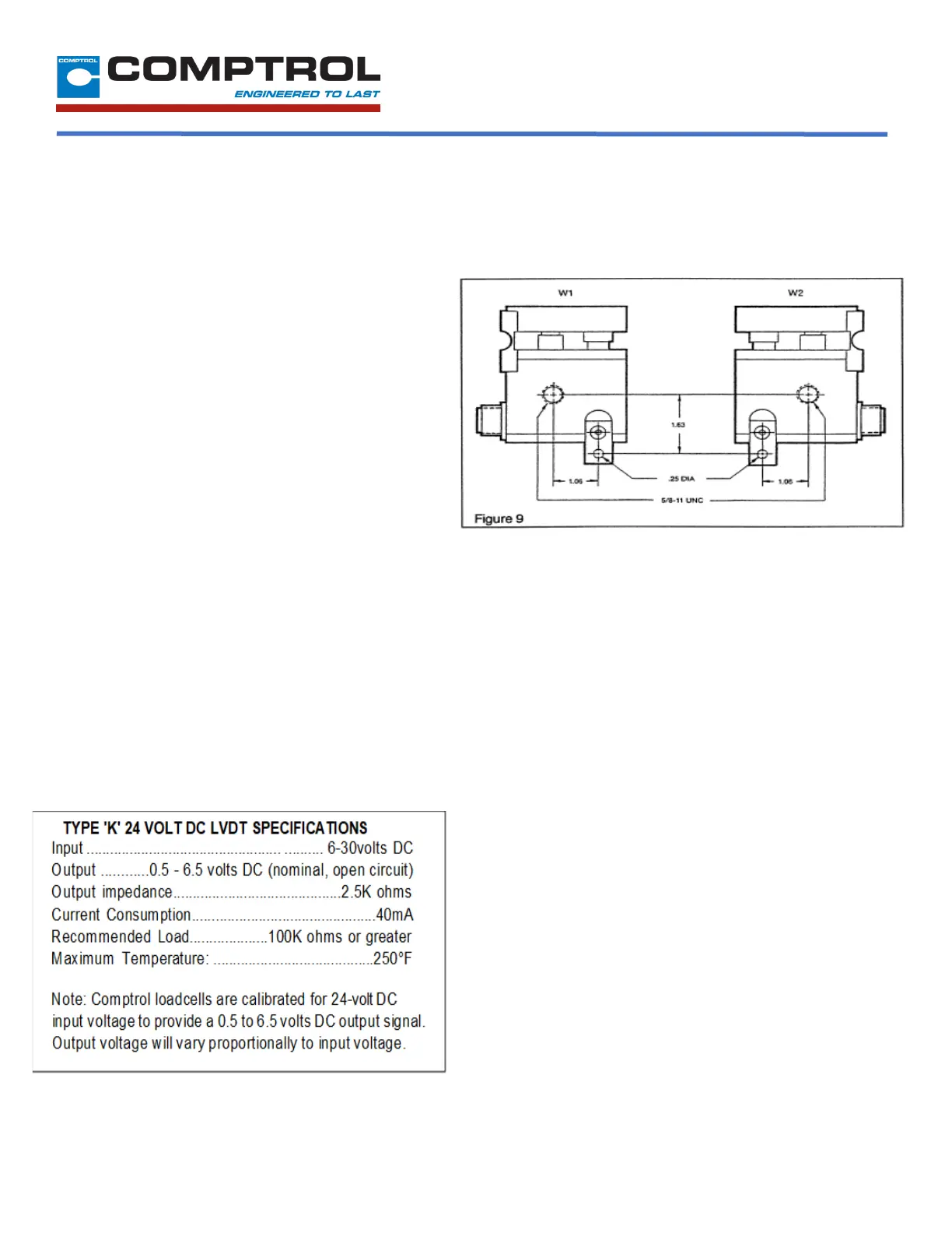
Tensioncells are designated as ‘W1” and “W2”, one
being the mirror image of the other to provide for
mounting between two fixed walls. (See Figure 9.)
Comptrol Wall Mounted Tensioncells are mounted to a
base assembly by a 5/8-11 UNC bolt which is in line with
the centerline of the measuring roll shaft. This allows the
Tensioncell to be rotated around the centers of the
measuring roll and mounting bolt to achieve the proper
mounting angle. (Description of Operation on Page 3)
A locating tab prevents the Tensioncell from rotating and
secures it in a permanent location. It also provides a
means of repeating rotatory position when the
Tensioncell needs replacement. (See Figure 9)
To Install Tensioncells:
1. Check that mounting surfaces to which the
Tensioncells are to be mounted are flat to within
.002-inch T.I.R.
2. Refer to Figure 10 for the size, location and
orientation of the Tensioncell Base Assembly
mounting holes to be drilled and tapped in the
stands or base structures.
3. Drill and tap the holes in the stand or base
mounting structure to accept the Tensioncell Base
Assembly.
4. Mount the Tensioncell Base Assembly to the stand
or base mounting structure.
5. Fasten the Tensioncell to the Base Assembly with a
5/8- 11 x1-1/4 Hex Head Cap Screw.
6. Rotate the Tensioncell to the proper mounting
angle and tighten the mounting bolt. (Refer to N on
on the calibration sheet for the proper mounting
angle)
 Loading...