MODEL 36, TYPE B & C
SINGLE RANGE TENSIONCELLS
INSTRUCTION MANUAL A-279
5
Copyright 2023 - Revised Comptrol All Rights Reserved
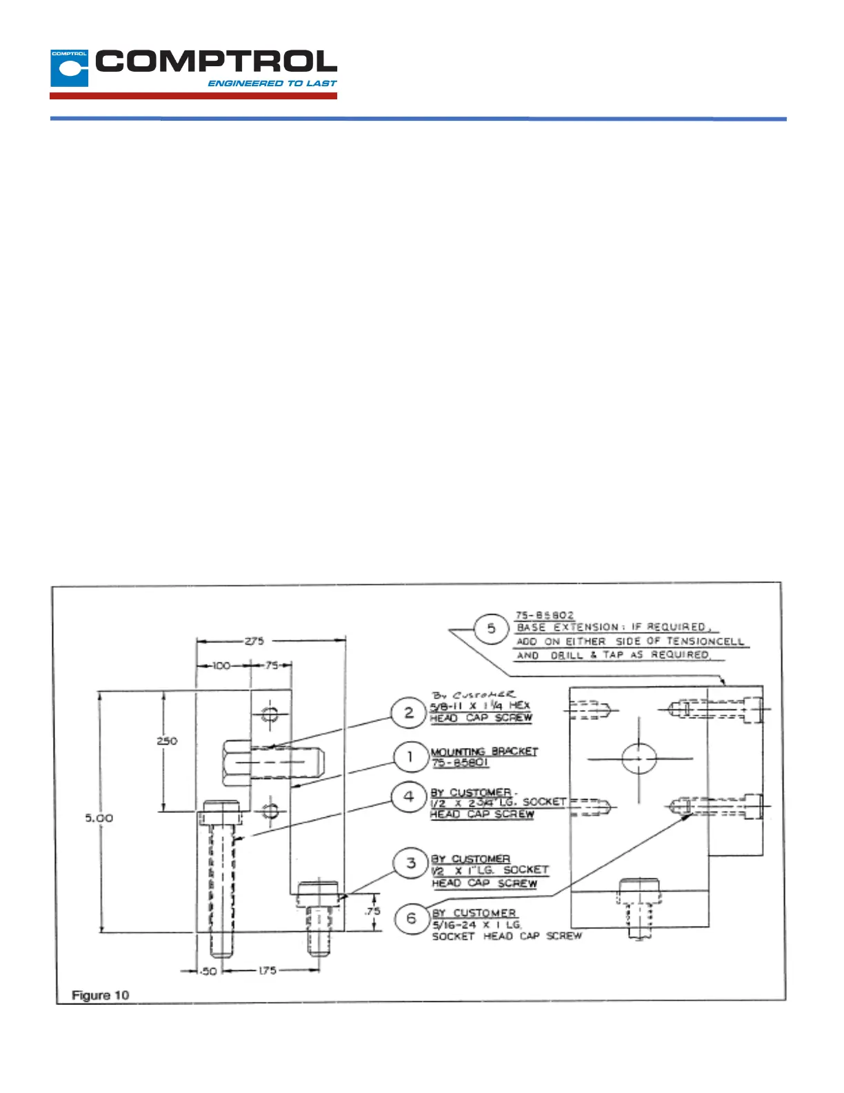
7. Drill
a #6
(.204)
hole concentric
with the 1/4"
hole
in the
locating tab.
8. Remove the Tensioncell and tap the hole for a 1/4 -20
thread.
9. Repeat steps 1 through 8 for the Tensioncell to be mounted
at the other end of the measuring roll.
10. Assemble the Tensioncell onto the end of the measuring
roll shaft.
11. Position the roll with the Tensioncells on the machine and
fasten with the mounting bolt.
12. Rotate the Tensioncell to the proper mounting angle and
tighten the mounting bolts.
13. Lock the locating pad for each Tensioncell against the
machine frame using the 1/4-20 X 1/2” socket head cap
screw.
14. Tighten the shaft in the mounting block on the “W1” unit.
(The shaft end at “W2” is left free to allow it to move as the
shaft expands with the temperature change).
II-E MECHANICAL ALIGNMENT
Align the sectional measuring roll to avoid any
mechanical binding or friction. The measuring roll must
be level and perpendicular to the path of the strip
material for accurate measurement.
The Mechanical Stops are fixed for the required travel of
the Load Table.
II-F ELECTRICAL INSTALLATION
(Read the entire electrical wiring procedure before
proceeding.)
1. Turn off all electrical power to the loadcell.
2. Use twisted two conductor signal cable, Belden 9402
or equivalent, in conduit from the LVDTs to the control
panel.
3. Observing correct polarity, connect the positive (+)
input lead to Pin A and the negative (-) input lead to
Pin B. (See Figure 4)
(Continued on page 6)
 Loading...