OPERATING ELEMENTS AND FUNCTIONS (CONTINUATION)
Q4M/Q8M
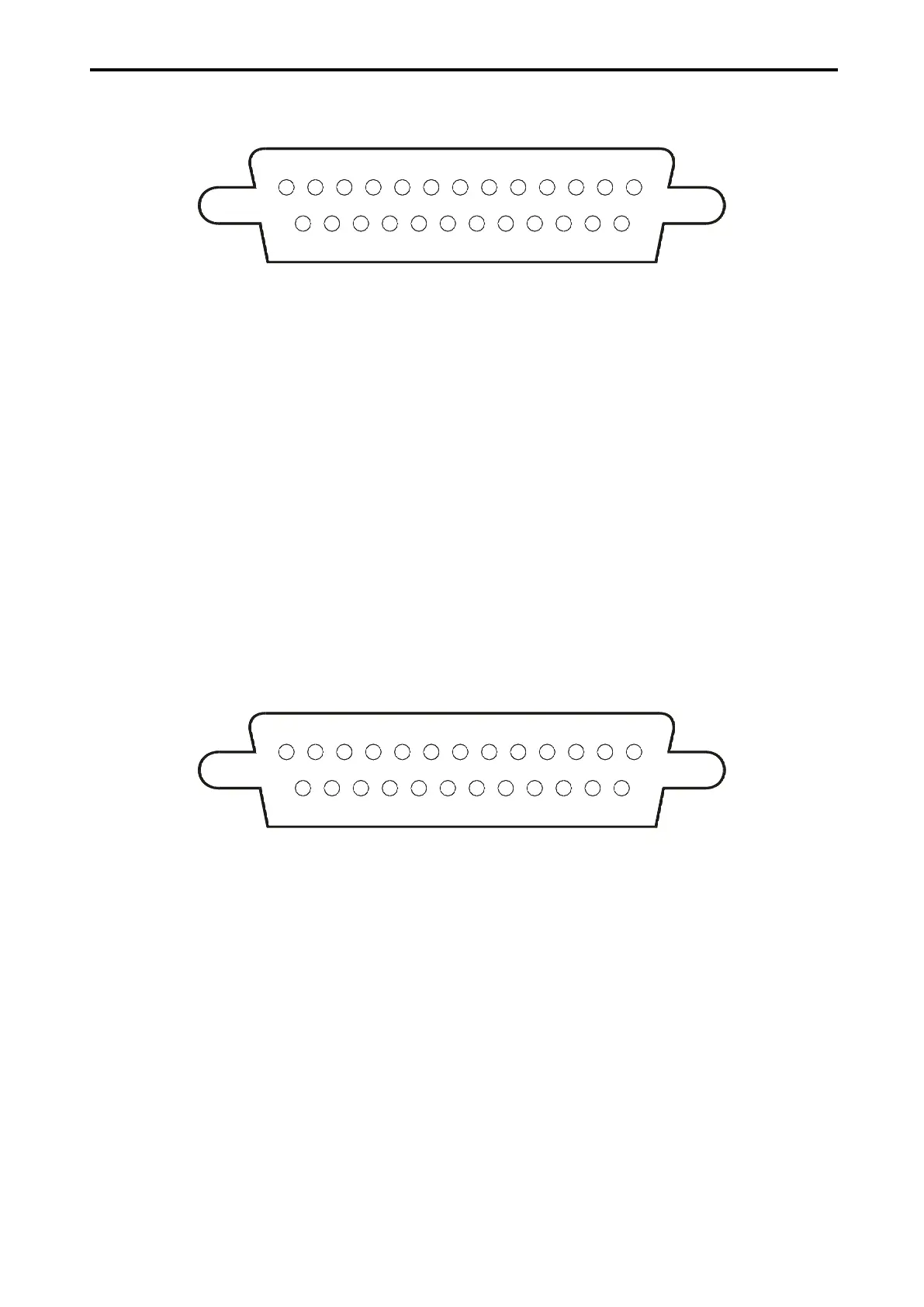
Pict. 5: Alarm connector CANNON 25 for Q4M
13 12 11 10 9 8 7 6 5 4 3
141516171819202122232425
2 1
(1) Alarm output – normally open contact 1
(2) Reserve
(3) Alarm input 1
(4) Alarm input 3
(5) Reserve
(6) Reserve
(7) Common conductor – ground (GND)
(8) Reserve
(9) Reserve
(10) Reserve
(11) Reserve
(12) Common conductor – ground (GND)
(13) Common conductor – ground (GND)
(14) Alarm output – normally open contact 2
(15) Reserve
(16) Alarm input 2
(17) Alarm input 4
(18) Reserve
(19) Reserve
(20) Common conductor – ground (GND)
(21) Reserve
(22) Reserve
(23) Reserve
(24) Reserve
(25) Common conductor– ground (GND)
Pict. 6: Alarm connector CANNON 25 for Q8M
13 12 11 10 9 8 7 6 5 4 3
141516171819202122232425
2 1
(1) Alarm output – normally open contact 1
(2) Reserve
(3) Alarm input 1
(4) Alarm input 3
(5) Alarm input 5
(6) Alarm input 7
(7) Common conductor – ground (GND)
(8) Reserve
(9) Reserve
(10) Reserve
(11) Reserve
(12) Common conductor – ground (GND)
(13) Common conductor – ground (GND)
(14) Alarm output – normally open contact 2
(15) Reserve
(16) Alarm input 2
(17) Alarm input 4
(18) Alarm input 6
(19) Alarm input 8
(20) Common conductor – ground (GND)
(21) Reserve
(22) Reserve
(23) Reserve
(24) Reserve
(25) Common conductor – ground (GND)