OPERATING ELEMENTS AND FUNCTIONS
Q4M/Q8M
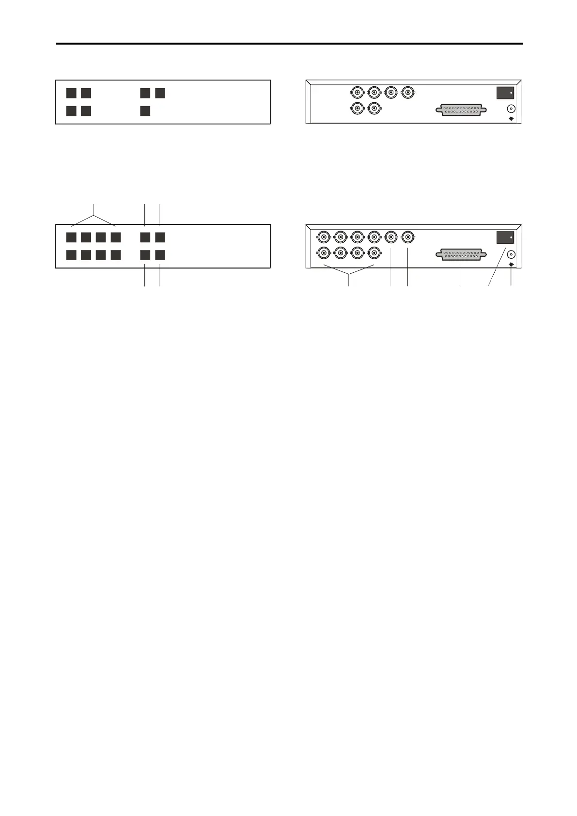
Pict.1: Front panel Q4M
MENU3 4
1 2 QUAD SEQ
QUAD PROCESSOR
Q4M
Pict.2: Front panel Q8M
QUAD2
MENU5 76 8
1 32 4 QUAD1 SEQ
DUAL PAGE QUAD PROCESSOR
Q8M
1 2 3
5
4
1. 1 - 8
Press the button 1 – 8 to display the appro-
priate camera image.
2. QUAD1
Press the button QUAD1 to display the split
screen containing cameras 1 – 4.
3. SEQ
Press the button SEQ to start the automatic
camera switching, according to the pro-
grammed sequence.
4. QUAD2
Press the button QUAD2 to display the quad
screen containing cameras 5 – 8 (only for
quads Q8M).
5. MENU
Press the button MENU to display the control
menu on the screen.
Pict.3: Back panel Q4M
IN 1
QUAD
MAIN
ALAR M
IN 3
IN 4 IN 2
POW ER
12V
-
+
Pict.4: Back panel Q8M
IN 1
QUAD
MAIN
ALAR M
IN 3IN 5IN 7
IN 8 IN 6 IN 4 IN 2
POW ER
12V
-
+
6
7 8 9 10
11
6. IN1 – IN8
Video inputs for cameras 1 – 8.
7. QUAD
Quad screen video output.
8. MAIN
Main video output.
9. ALARM
Connector for connecting alarm inputs and
outputs. This connector enables connecting
of alarm contact makers, sensors, etc.
10. POWER
Press the switch POWER to start the quad.
11. 12V
Connector for connecting power supply.