Do you have a question about the Conotec FOX-2004 and is the answer not in the manual?
Chart detailing the operational states of COMP, Defrost, and FAN.
Configuration for user mode parameters like HSP, LSP, DIS, DIF, DLT, COR, SER, DSP, LOCK.
Configuration for installer mode parameters including D.DE, D.OR, D.TP, D.OF, D.ON, D.DT, D.ST.
Configuration for installer mode parameters F.ST and F.DE.
General warnings and cautions for safe operation and installation of the controller.
Specific warnings regarding electric shock hazards during maintenance and operation.
Explanation of error codes (E1, E2, SE1, SE2, HH1, HH2, LL1, LL2) and their meanings.
Diagrams showing the controller's physical dimensions and required panel cutout size.
Recommended ambient temperature and humidity ranges for optimal operation.
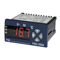
The CONOTEC FOX-2004 is a digital temperature controller designed for precise temperature management in various applications. It offers comprehensive control over temperature, defrost cycles, and fan operation, making it suitable for systems requiring accurate environmental regulation.
The FOX-2004 primarily functions as a temperature controller, capable of managing both cooling (COMP control) and defrosting (Defrost control) processes. It also integrates a FAN control function to regulate air circulation. The device utilizes two NTC sensors to monitor temperatures, allowing for independent measurement of the main temperature and the defrost temperature.
The controller operates within a temperature range of -55.0°C to +99.9°C. It features a clear digital display that shows the current temperature and allows users to easily set desired parameters. Output relays are provided for connecting to external components such as compressors, defrost heaters, and fans, with a maximum output capacity of 250VAC 2A. For higher loads, the use of a power relay or magnet is recommended to ensure reliable operation.
The FOX-2004 offers a user-friendly interface with distinct modes for operation and configuration.
In the standard user mode, the device displays the current temperature. Pressing the "set" key allows the user to view and adjust the setting temperature. Once adjusted, pressing "set" again confirms the change, indicated by an "O-K" message, and the new setting is remembered. This mode is designed for quick and easy adjustments of the primary temperature setpoint.
For more advanced configuration, the installer mode provides access to a wide range of programmable parameters. This mode is accessed by pressing the "set" key for more than 5 seconds, which will display "E81," "E82," or "E83." Users can then navigate through these categories using the "up" and "down" arrow keys.
E81 Parameters (General Settings):
E82 Parameters (Defrost Settings):
E83 Parameters (FAN Settings):
The FOX-2004 supports manual defrost initiation and termination. To start a manual defrost, press the "down" arrow key for more than 3 seconds. The K2 LED will flicker, indicating the defrost cycle has begun. To stop a manual defrost, press the "down" arrow key for more than 3 seconds again during an active manual defrost, or it will automatically stop after the configured defrost time.
The device can display the main temperature sensor reading, the defrost sensor reading, or alternate between the two every 2 seconds, depending on the DSP setting. Pressing the "up" arrow key for more than 1 second in the present temperature display mode will cycle through these display options.
The FOX-2004 is designed for reliability, but proper installation and handling are crucial for its longevity and accurate performance.
The controller provides clear error codes on its display to assist in diagnosing issues:
These error codes help users or technicians quickly identify the nature of a problem, facilitating troubleshooting and maintenance.
The manual emphasizes several precautions for installation and wiring to ensure optimal performance and safety:
By adhering to these guidelines, users can ensure the FOX-2004 operates reliably and accurately, minimizing the need for frequent maintenance and extending its operational lifespan. The device is built to provide consistent temperature control, and proper care ensures its continued performance.
| Control Mode | PID, On/Off |
|---|---|
| Input Type | Thermocouple, RTD |
| Display | LED |
| Dimensions | 48 x 48 x 100 mm |
| Number of Outputs | 2 |
| Output | Relay, SSR |
| Power Supply | 100-240VAC, 50/60Hz |
| Communication | RS-485 |