en Installation instructions
28
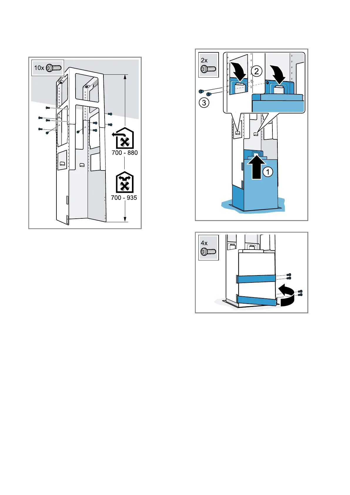
Installing the lower support frame
▶
Attach the upper and lower section of the support
frame at the specified total height using 10 screws.
– Ensure that the lower support frame is in the cor-
rect position.
– The open side must be facing the hob's control.
Tip:If you undo the fastening screws, you can retroact-
ively realign the support frame.
Installing the appliance
1.
Hook the appliance from below into the support
frame.
Ensure that the power cord is not trapped.
2.
Attach the appliance to the support frame using 2
securing screws.
3.
Hook in the retaining clips and screw them in tightly.
Piping
Note:If you are using an aluminium pipe, smooth the
connection area beforehand.
We recommend the piping with an exhaust air pipe dia-
meter of 150mm.
Establishing the exhaust air connection (exhaust air
pipe, 150mm diameter)
▶
Fit the exhaust air pipe directly to the air-pipe con-
nector and seal the joint.
Establishing the exhaust air connection (exhaust
pipe, 120mm diameter)
1.
Secure the reducing connector to the air-pipe con-
nector.
2.
Secure the exhaust air pipe to the reducing con-
nector.
3.
Seal the joints.