ATTENZIONE!!!
• Leggere attentamente il manuale prima dell’utilizzo e l’installazione.
• Questi strumenti devono essere installati da personale qualificato, nel
rispetto delle vigenti normative impiantistiche, allo scopo di evitare danni
a persone o cose.
• Prima di qualsiasi intervento sullo strumento, togliere tensione dagli
ingressi di alimentazione e dalle uscite relè dove presenti.
• Il costruttore non si assume responsabilità in merito alla sicurezza
elettrica in caso di utilizzo improprio del dispositivo.
• I prodotti descritti in questo documento sono suscettibili in qualsiasi
momento di evoluzioni o di modifiche.
Descrizione
• Relè differenziale di terra tipo A
• Misure in vero valore efficace (TRMS)
• Filtro di terza armonica
• Esecuzione modulare, 3 moduli per guida DIN
• LED verde di segnalazione alimentazione (ON)
• Toroide esterno serie CT-1
• Funzionamento con sicurezza positiva per ciascun relè (impostabile)
• Visualizzazione dei valori della corrente differenziale
• Display LCD retroilluminato (verde, giallo, rosso)
• 4 LED per l’indicazione di TRIP
• Pulsanti TEST e RESET sul fronte
• 4 relè indipendenti per il controllo degli interruttori dei quattro canali
di ingresso
• Grafico andamento istantaneo della misura della corrente per ogni canale
• Log eventi intervento corrente di guasto
• Porta di comunicazione RS-485 (protocollo Modbus RTU)
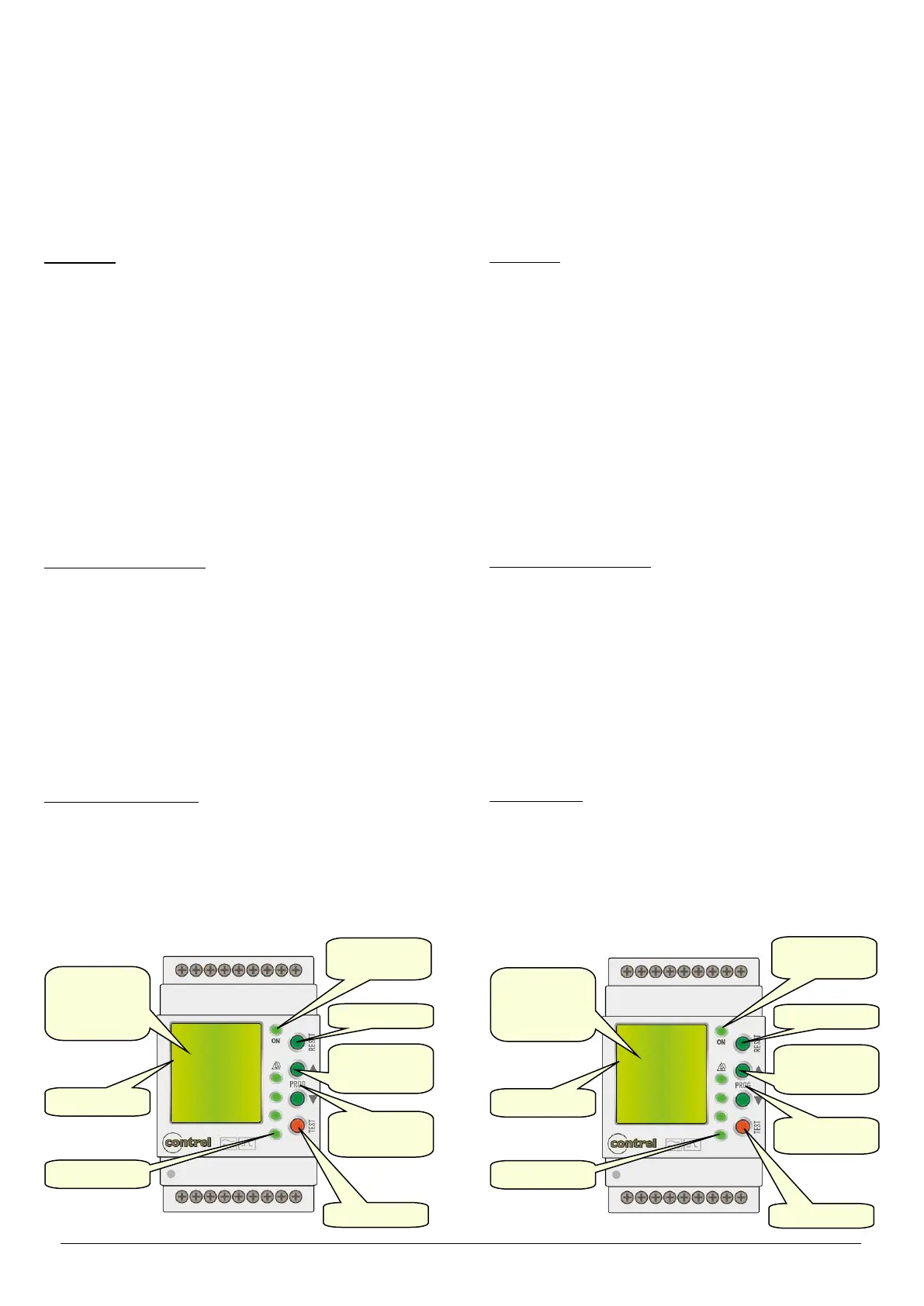
Display and LED functions
Grazie al display LCD, l'utente può visualizzare i valori della corrente
differenziale, TRMS con filtro, valori MAX, TDH, fattore di cresta), grafici a
barre, Log eventi, gli allarmi e accedere alle impostazioni.
• Verde: corrente rilevata inferiore alla soglia impostata
• Giallo:
- rilevata corrente superiore alla soglia di PRE-ALLARME ma inferiore
alla soglia TRIP
- circuito aperto del toroide esterno (o non collegato)
• Rosso:
- intervento del relè di TRIP per il superamento della I∆n impostata
- lettura valore fuori scala
- TEST, provoca l’intervento del relè
Funzione dei tasti frontali
Tasto RESET – Serve per il ripristino dei relè dopo l‘intervento, per uscire dal
menu di impostazione.
Tasto TEST – Provoca l’intervento dei relè, per confermare una scelta.
Tasto PROG – Serve per entrare nel menu di impostazione, per lo
scorrimento delle pagine.
Tasti ▲e ▼– Servono per lo scorrimento fra le pagine video, per la
selezione tra le possibili scelte e per la modifica di impostazioni
(incremento/decremento).
WARNING!
• Carefully read the manual before the installation or use.
• This device is to be installed by qualified personnel, complying to current
standards, to avoid damages.
• Before any maintenance operation on the device, remove supply inputs.
• The manufacturer cannot be held responsible for electrical safety in case
of improper use of the equipment.
• Products illustrated herein are subject to alteration and changes without
prior notice.
Description
• Earth leakage relay type A
• Measuring in true effective value (TRMS)
• Third harmonic filtering
• Modular DIN-rail housing, 3 modules
• Green power LED indicator (ON)
• External residual current transfomer CT-1 series
• Fail safe function for each four relays (settable)
• Visualization instant leakage values
• Backlighted LCD display (green, yellow, red)
• 4 indicator LEDs for tripping
• On the front panel, TEST and RESET button
• Four independent relays to control the circuit breakers of the four
channels
• Instantaneous bar-graph of current measurement for each channel
• Log tripped residual current
• RS-485 communication (Modbus RTU protocol)
Display and LED functions
Thanks to LCD display, the user can view very quickly the measurements
(instant leakage values, filter TRMS, MAX values, THD, crest factor), the
graph bar, the Log, the alarms and can access to all settings.
• Green: detected current lower than threshold
• Yellow:
- detected current higher than PRE-ALARM threshold but lower than
TRIP threshold
- open residual current transformer circuit (or not connected)
• Red:
- detected current higher than TRIP threshold and relay activation
- current leakage read off scale
- TEST, causes tripping of the relay
Front keyboard
RESET key – To reset the relay after tripping, used to exit from settings
menu.
TEST key – Causes tripping of the relays, to confirm a choice.
PROG keys – Used to enter into settings menu, to scroll display pages.
▲and ▼ keys – Used to switch between visualization modes, to select
among possible choices and to modify settings (increment/decrement).
 Loading...