© 2000 CONTRIVE • B1401.EN 0211 9 www.contrive.it
Q510 – AUTO SHUT-OFF MODE
Behavior after an automatic shut-off. In AUTOMATIC mode a complete burner
restart cycle is deployed, performing the test of the whole system, as per Standard
requirements, within 24 hours of continuous operation.
In MANUAL mode the burner waits for reset.
Q512 – FLAME LOSS
Determines the behavior at flame loss during normal burner operation.
For burners with occasionally unstable flame signal a single recycle (including
prepurge) or direct respark can be attempted. The setting is to be determined on
the basis of burner capacity and relevant application standard.
Q602 – POSTPURGE TIME
Follow EN 676 requirements to set correct postpurge time in forced draught
burners. Any air valve and/or butterfly valve controlled by external process must
be kept open during the whole postpurge time.
During this time an illegal flame test is carried out.
Q701 – ZONE (SEGMENT)
Communication identifier: group or zone belonging the burner control.
All alphanumeric (uppercase/lowercase) characters are valid identifiers.
Q702 – UNIT (NODE)
Communication identifier: burner control unit within a given area, group or zone.
All alphanumeric (uppercase/lowercase) characters are valid identifiers.
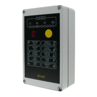
Q703 – BAUD RATE
Communication baud rate: 4800, 9600, 19200, 38400.
Q704 – COMMUNICATION TIMEOUT
Communication timeout up to 1000 seconds (4” step). Set 0 to disable.
Q801 – BURNER TYPE
Selecting OIL type burner the ignition device will be activated also during the
prepurge to allow the detection of oil leakage that will be ignited, leading to an
illegal flame detection. Application and settings must be made in accordance to
EN 230 (or other relevant standard) requirements.
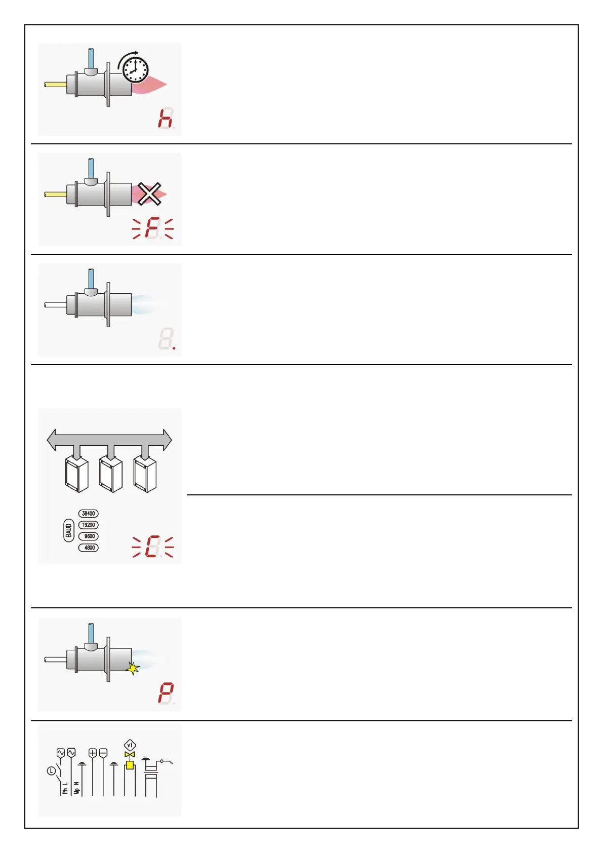
Q001 – POWER SUPPLY VOLTAGE
Power supply must be wired at terminal 01 and 02, for burner control unit and
loads (gas valve and ignition transformer), both protected by the embedded fuse.
Optional safety interlock limits could be wired on the main supply phase.