© 2000 CONTRIVE • B1401.EN 0211 5 www.contrive.it
GAS BURNER
When the equipment is used for gas burners, the prescriptions set forth in the European Standard EN298 (including
any further revision) must be completely fulfilled, along with the specific requirements of any National regulation in
force in the Country where the equipment is installed.
Combustion air and optional process limits are controlled by external circuitry.
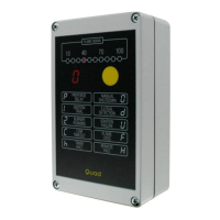
A complete self test is deployed at power-on and at any reset from lockout, possible failures are reported on the
front panel display.
Depending on the configuration, the system starts the prepurge time (autostart) or waits for manual start-up
(standby mode). A flame simulation test is carried out during Prepurge.
The gas valve will be activated only if the ignition device is detected (power supply current) during preignition time.
The gas valve remains open during the programmed safety time, if a valid flame signal is detected within the safety
time the valve is kept open: the burner is on. The system will lockout if no flame is detected.
Flame quenching during burner operation will force the system to lockout, recycle or respark.
There are different options to stop the burner:
switching off the power supply;
pressing the front panel button (manual shutdown);
remote communication command (remote halt);
internal timer (if enabled).
A postcombustion time (max 20 seconds) is allowed after a lockout or shutdown request, followed by pospurge.
The device can stop the burner after programmed auto shutoff time (5m to 20h50m) of continuous operation and
restart again, providing that all the equipment and burner safety tests are successfully performed.
BLOWER THERMAL PROTECTION
ALL SAFETY SWITCHES SHOULD BE APPROVED AS LIMIT CONTROLS
THE USE OF ELECTRONIC SWITCHES MAY CAUSE ERRATIC OPERATIONS
 Loading...