EasyManua.ls Logo

Control 4 C4-DIN-8FPD-E - User Manual

Control 4 C4-DIN-8FPD-E
4 pages
Print Icon
To Next Page IconTo Next Page
Loading...
8-Channel
Forward Phase Dimmer
Operation and Configuration Guide
Introduction
The Control4® 8-Channel Forward Phase Dimmer (C4-DIN-8FPD-E) controls up
to eight devices from one module in the Control4 system. It installs in a panelized
backbox using typical wiring standards and communicates to the Control4 system
using a Cat5 Ethernet connection.
Note: For optimal product and network security, we recommend using this
product with Control4 OS 3.2.2 or newer.
Dimming mode configuration
Each channel on the 8-Channel Forward Phase Dimmer can be set to two dierent
dimming modes:
Switch Mode—Only allows the load to be set to 100% or o
Dimming Mode—Forces the channel into forward-phase (leading edge)
dimming
SSL 7A Mode—Sets dimming parameters complaint to NEMA SSL 7A
Note: Dimming mode should only be used with dimmable loads.
Note: By default, all channels on the 8-Channel Forward Phase Dimmer
are set to Switch Mode to prevent inadvertent dimming of non-
dimmable loads.
With the buttons on the front of the module, configure the mode for each channel:
1 Press the CH1 and CH8 buttons simultaneously.
2 All channel LEDs will indicate the their current dimming mode:
Solid yellow—Switch Mode
Solid green—Forward Phase Mode
Solid magenta—SSL 7A Mode
3 Click each channel button to cycle through the dimming mode.
4 Once each channel is set as desired, exit the configuration mode by pressing
and holding the Module Override button briefly.
The previous procedure should be repeated anytime that a module is rewired or a
load type changes.
Note: Once the module has been identified into a project, it is no
longer possible to configure the dimming mode from the module. The
dimmable/non-dimmable load type settings in Composer must be used
to configure the dimming mode.
Note: When first identifying a module into a project, if the dimming
mode of the light in Composer conflicts with the dimming mode of
the corresponding channel on the module, a warning will be presented
forcing the user to choose the appropriate dimming mode.
Composer Pro configuration and reports
Use Composer Pro to define the properties of each 8-Channel Forward Phase
Dimmer, its location in a panel, and the loads that are connected to it. Composer
Pro can then be used to generate Panel Reports, Module Reports, and Load
Schedule Reports. These reports are essential to ensuring that each 8-Channel
Forward Phase Dimmer is properly installed in the correct location and wired to
the appropriate loads. Please refer to the Composer Pro User Guide for detailed
information.
LEDs
During normal operation, the indicator lights on the front of the 8-Channel
Forward Phase Dimmer communicate the status of the device.
Indicator LED color Status Notes
Module Override Blue Power on, normal
operation
Black O
Red Overtemp Fault See “Faults” section
below
Channels Blue Load on
Black Load o
Red Overcurrent Fault or
Overtemp Fault
See “Faults” section
below
Yellow Over–Wattage Fault "
Cyan No Power On Phase
Fault
"
Flashing
green
Firmware updating
Green Firmware update
complete
Link/Activity Solid green Link
Orange Activity
Flashing
green
Firmware updating Flashing gets faster
as update proceeds
Channel and Module Override buttons
During normal operation, the buttons on the front of the 8-Channel Forward
Phase Dimmer behave in the following manner:
Button Action Result
CH1-CH8 Click Toggles the load on and
o.
Hold Ramps/fades the load (if
dimmable).
Module Override Click Toggles between the
module override scene
and all channels o.
Hold for five (5) seconds Sets the module override
scene to current chan-
nel levels. The Module
Override LED will blink
rapidly to indicate that
the override scene has
been saved.
The following button tap sequences are available using the CH1 and CH8 buttons.
Function CH1 CH8 CH1
Identify 4
Reboot device 15
Factory reset 949
Question and Answer IconNeed help?

Do you have a question about the Control 4 C4-DIN-8FPD-E and is the answer not in the manual?

Summary

Composer Pro Configuration

LED Indicators

Describes the LED indicators on the front of the 8-Channel Forward Phase Dimmer and their statuses.

Introduction to 8-Channel Dimmer

System Requirements

Recommends using the product with Control4 OS 3.2.2 or newer for optimal security.

Dimming Mode Configuration

Switch Mode

Allows the load to be set to 100% or off.

Dimming Mode

Forces the channel into forward-phase (leading edge) dimming.

SSL 7 A Mode

Sets dimming parameters compliant to NEMA SSL 7A.

Note on Dimmable Loads

Dimming mode should only be used with dimmable loads.

Default Mode

By default, all channels are set to Switch Mode to prevent inadvertent dimming of non-dimmable loads.

Module Configuration Limitation

Once the module has been identified into a project, dimming mode configuration is only possible via Composer.

Dimming Mode Conflict Warning

A warning is presented if the Composer dimming mode conflicts with the module's channel mode.

Channel and Module Override Buttons

Button Actions

Describes the actions and results of pressing the CH1-CH8 and Module Override buttons.

Reset Button Functions

Special Reset Activities

Describes special activities accomplished by pressing and holding specific buttons while clicking the Reset button.

Fault Conditions

Overtemp Fault

Occurs if the module reaches an unsafe operating temperature, causing all loads to turn off.

Overcurrent Fault

Occurs due to a large current spike on a channel, causing the load on that channel to turn off.

Over-Wattage Fault

Occurs if wattage exceeds the individual channel threshold, causing the load to turn off.

No Power On Phase Fault

Fault Description

Occurs if there is no zero cross detected on Line 2 (L and N).

Manual Overrides

Override Scene

The module's stored scene, defaulting to all loads on at 100%.

Module Override Button

Toggles attached loads between the stored override scene and all loads off.

Auxiliary Override Contacts

Allows control via a standard line-voltage toggle switch wired to the Aux In terminals.

Channel Override Buttons

Provide individual control to toggle each load between its preset level and off.

Troubleshooting Common Issues

Module Not Powering On

Verify circuit breaker and Line 1 connection.

Load Not Turning On

Check wiring, fault conditions, and bulb status.

Loads Not Turning Off

Verify terminal block jumpers between red and black terminal blocks.

Module Overheating

Verify load ratings have not been exceeded and module has proper ventilation.

Additional Resources

Support Resources

Lists Control4 Knowledgebase, forums, Technical Support, website, and Composer Pro documentation.

Regulatory and Safety Information

Information on reviewing regulatory information for Control4 products.

Patent Information

Details on applicable patents available at ctrl4.co/patents.

Warranty Information

Details on warranty are available at ctrl4.co/warranty.

Document Version

Open the URL or scan the QR code for the latest version of this document.

Overview

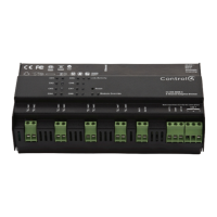
The Control4 8-Channel Forward Phase Dimmer (C4-DIN-8FPD-E) is a panelized lighting control module designed to manage up to eight loads within a Control4 smart home system. It utilizes a Cat5 Ethernet connection for communication with the Control4 system and is recommended for use with Control4 OS 3.2.2 or newer for optimal security and performance.

Function Description:

This device primarily controls lighting loads by providing either 100% on/off (Switch Mode) or forward-phase (leading edge) dimming (Dimming Mode). It also supports SSL 7A Mode, which sets dimming parameters compliant with NEMA SSL 7A standards. By default, all channels are set to Switch Mode to prevent accidental dimming of non-dimmable loads. The dimming mode for each channel can be configured directly on the module using its front panel buttons, though once the module is identified in a Composer project, dimming mode configuration must be done via Composer Pro.

Important Technical Specifications:

The device is designed to protect itself and connected loads from various fault conditions, including:

  • Overtemp Fault: Occurs when the module reaches an unsafe operating temperature, typically indicating it's exceeding its load ratings. All attached loads turn off, and the Channel LED and Module Override LED turn red. The fault clears automatically once a safe temperature is reached, but loads do not automatically turn back on.
  • Overcurrent Fault: Triggered by a significant current spike on an individual channel, which can be caused by a short circuit, high in-rush current, a burning incandescent bulb, or dimming a non-dimmable load. The faulted load turns off, and the Channel LED turns red. The fault can be cleared by turning the load back on. If the fault reoccurs within 10 seconds, it's considered ongoing and requires addressing the underlying problem before clearing.
  • Over-Wattage Fault: Occurs if the wattage on an individual channel exceeds 1000W for 10 seconds. The faulted load turns off, and the channel LED turns yellow. The fault can be cleared by turning the load back on.
  • No Power On Phase Fault: Occurs if no zero cross is detected on Line 2 (L and N), affecting channels 5-8. The channel LEDs turn solid cyan, and the fault cannot be cleared until Line 2 (L and N) are properly connected.

Usage Features:

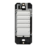
The front panel of the 8-Channel Forward Phase Dimmer features indicator LEDs and buttons for local control and configuration.

LED Indicators:

  • Module Override LED (Blue): Indicates normal operation.
  • Module Override LED (Black): Off.
  • Module Override LED (Red): Indicates an Overtemp Fault.
  • Channel LEDs (Blue): Load on.
  • Channel LEDs (Black): Load off.
  • Channel LEDs (Red): Overcurrent Fault or Overtemp Fault.
  • Channel LEDs (Yellow): Over-Wattage Fault.
  • Channel LEDs (Cyan): No Power On Phase Fault.
  • Flashing Green (Module Override/Link/Activity): Firmware updating.
  • Green (Link/Activity): Firmware update complete.
  • Solid Green (Link/Activity): Link established.
  • Orange (Link/Activity): Activity.

Button Functionality (Normal Operation):

  • CH1-CH8 Buttons (Click): Toggles the corresponding load on and off.
  • CH1-CH8 Buttons (Hold): Ramps/fades the load (if dimmable).
  • Module Override Button (Click): Toggles between the module override scene and all channels off.
  • Module Override Button (Hold for 5 seconds): Sets the module override scene to current channel levels. The Module Override LED blinks rapidly to confirm the scene has been saved.

Button Tap Sequences (using CH1 and CH8 buttons):

  • Identify (4 taps on CH1): Used for device identification within Composer Pro.
  • Reboot device (15 taps on CH1): Restarts the device.
  • Factory reset (9 taps on CH1, 4 taps on CH8, 9 taps on CH1): Restores the device to factory settings. This should only be performed under the direction of Control4 Technical Support.

Dimming Mode Configuration (on device):

  1. Press CH1 and CH8 buttons simultaneously.
  2. All channel LEDs indicate their current dimming mode:
    • Solid yellow: Switch Mode
    • Solid green: Forward Phase Mode
    • Solid magenta: SSL 7A Mode
  3. Click each channel button to cycle through the dimming mode.
  4. Once desired modes are set, exit by pressing and holding the Module Override button briefly. This procedure should be repeated if the module is rewired or load types change.

Manual Overrides:

  • Override Scene: A stored scene within the module that can be activated to set all loads to a predefined state (default is 100% on). This scene can be configured via Composer Pro or the module's buttons.
  • Module Override Button: Toggles all attached loads between the stored override scene and off.
  • Auxiliary Override Contacts (Aux In and Aux Out): These terminals allow wiring a standard line-voltage toggle switch for external control. Flipping the switch toggles between the stored override scene and off. Multiple modules can share an auxiliary override switch if on the same electrical phase.
  • Channel Override Buttons: Provide individual control, toggling loads between a preset level and off, or ramping/fading when held.

Maintenance Features:

  • Reset Button: A single click of the recessed Reset button (requires a paperclip) is equivalent to power cycling the device. Holding specific buttons while clicking Reset allows for special activities:
    • CH7 + Reset: Disables DHCP and forces the IP address to 192.168.1.200.
    • CH8 + Reset: Toggles between Enable/Disable DHCP.
    • Module Override + Reset: Restores the factory image (use only when directed by Control4 Technical Support).
  • Troubleshooting: The manual provides a troubleshooting guide for common issues like the module not powering on, loads not turning on/off, or module overheating, with corresponding possible solutions.
  • Composer Pro Integration: Composer Pro is used to define module properties, location in a panel, and connected loads. It also generates Panel Reports, Module Reports, and Load Schedule Reports, which are crucial for proper installation and wiring verification.
  • Firmware Updates: Indicated by flashing green LEDs, ensuring the device remains up-to-date with the latest features and bug fixes.

Control 4 C4-DIN-8FPD-E Specifications

General IconGeneral
BrandControl 4
ModelC4-DIN-8FPD-E
CategoryDimmer
LanguageEnglish

Related product manuals