Introduction
The Control4 CA-10 Automation Controller is the most powerful member of
Control4’s award-winning line of controllers, designed to provide the speed,
memory, and reliability required to power the most demanding projects. The
CA-10 raises the bar for home automation through:
• A powerful processor that provides great performance for the largest
projects.
• Redundant internal power supplies to reduce failures due to a power spike or
brown out.
• Dual solid state drives (SSD) with data replication to safeguard the
customer’s project and customizations.
• SSDs that are accessible behind a magnetically attached front panel for
eortless service.
• Dual network interface controllers to protect against switch, cable, or other
network failures.
• Redundant cooling fans to ensure quiet, worry-free performance.
• 5 year warranty, included.
Box contents
• CA-10 Automation Controller
• Power cord
• Rack ears (2) attached
• Cable ferrite clamps (2)
Specifications
Model number
C4-CA10
Connections
Network
2 × Ethernet—10/100/1000BaseT (redundant connections)
Storage
Dual 32 GB (minimum) solid-state drives (SSD) in RAID 1
configuration
USB port
2 USB 3.0 ports-1A
Power
Power requirements
AC power supply accepts 100-240V ~ 50-60 Hz (1A)
Power supplies
2 redundant power supplies with auto failover
Power consumption
Max 70W (239 BTU/hr)
Miscellaneous
Operating temperature
32 ˚F to 104 ˚F (0 ˚C to 40 ˚C)
Storage temperature
4 ˚F to 158 ˚F (-20 ˚C to 70 ˚C)
Fans
2 redundant fans
Fan dB level
Max: 44 dB
Dimensions (W × D × H) 17.5 × 10.125 × 1.72" (444 × 258 × 44 mm)
Weight
9.55 lb (4.33 kg)
Shipping weight
12 lb (5.44 kg)
Minimum OS version
Requires Control4 Smart Home OS 3.1 or newer
Warnings
Caution! To reduce the risk of electrical shock, do not expose this
apparatus to rain or moisture.
AVERTISSEMENT ! Pour réduire le risque de choc électrique, n’exposez
pas cet appareil à la pluie ou à l’humidité.
Caution! In an over-current condition on USB, the software disables
the output. If the attached USB device does not appear to power on,
remove the USB device from the controller.
AVERTISSEMENT ! Dans une condition de surintensité sur USB le
logiciel désactive la sortie. Si le périphérique USB connecté ne semble
pas s’allumer, retirez le périphérique du contrôleur.
For more information, visit the Products pages at dealer.control4.com.
Additional resources
The following resources are available for more support.
• Control4 Knowledgebase: kb.control4.com
• Dealer Forums: forums.control4.com
• Control4 Technical Support: dealer.control4.com/dealer/support
• Control4 website: www.control4.com
• Composer Pro documentation in online help or PDF format available on the
Dealer Portal under Support: ctrl4.co/docs
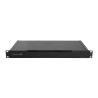
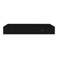
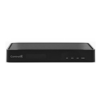
Front view
A Caution LED—The RGB status LED gives system status feedback. See
“Troubleshooting” in this document for LED status information.
B Link LED—The blue LED indicates that the controller has been identified in a
Control4 Composer project and is communicating with Director.
C Power LED—The blue LED indicates that AC power is connected. The
controller turns on immediately after power is applied to it.
D SSD LEDs—The red LED indicates an error with the SSD. See “Troubleshooting”
in this document for LED status information. The SSD LEDs are only visible
when or when the covered is removed.
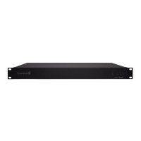
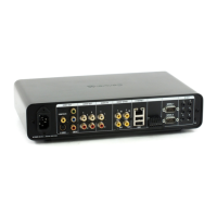
Back view
A Power port—AC power receptacle for an IEC power cord.
B ID button—Button used to identify the device in Composer Pro and reset the
controller. The ID button on the CA-10 is also an LED that displays feedback
useful during a factory restore. See “Troubleshooting” in this document.
C Reset button—Button used to factory reset the controller. See
“Troubleshooting” in this document.
D USB—Two USB 3.0 ports for external USB drives (e.g., FAT32-formatted
devices). See “Setting up external storage devices” in this document.
E ETHERNET—Two 10/100/1000 redundant Ethernet ports for local network
connection. See “Connecting the controller” in this document. These two ports
do not function as an Ethernet switch.
Installing the controller
Requirements:
• Ensure that the Ethernet network is in place before starting system setup.
• The controller requires two Ethernet network connections. When both are
connected, the controller communicates with other IP devices in the home
and access Control4 system updates over a redundant network connection.
• Composer Pro software version 3.1.0 or newer is required for configuration.
Mounting options:
• In-rack—The controller can be mounted in a standard equipment rack (1U).
Insert the controller into the rack space and secure it with 4 standard rack
screws (not included). Make sure the controller has adequate ventilation
(vents are on the front and back of the controller).
• Cabinet or shelf—The controller can be installed on a shelf or other hard
surface. Make sure the controller has adequate ventilation (vents are on the
front and back of the controller).
AA B C D E
CA
Resetting to factory settings
Caution! The factory reset process will remove the Composer project.
To restore the controller to the factory default image, perform the following
steps:
1 Insert one end of a paper clip into the small hole on the back of the
controller labeled Reset.
2 Press and hold the Reset button, the controller will reset and the Caution
LED will turn solid red.
3 Hold the button until the LED blinks double yellow, and then release it. This
should take 15 to 20 seconds. The LED blinks yellow while the factory restore
is running. When complete, the LED will turn o and the device will reset to
complete the factory restore process.
Restarting the controller
Press and hold the ID button for five seconds. The controller restarts.
Resetting the network settings
Caution: The network set process will remove any network
configuration and set the controller’s network settings to DHCP.
To reset the controller network settings to the default, follow these steps:
1 Disconnect power to the controller.
2 While pressing and holding the ID button on the back of the controller,
power on the controller.
3 Hold the ID button until the LED is solid orange, then immediately release
the button.
4 If during the boot sequence the LED stays orange, press and hold the ID
button until the LED blinks blue, and then release it.
Replacing a failed SSD
The dual SSDs are located behind the front panel of the CA-10 and can be
replaced in the field at the direction of Technical Support.
To replace an SSD, perform the following steps:
1 Remove the plastic front panel of the CA-10 by pulling it straight out from
the magnetic mounts.
2 The LED next to each SSD shows solid red when the drive is in a failed state.
Locate the drive with the red LED next to it.
3 Power down the controller.
4 Remove the screw holding in the SSD. The SSD will swing away from the
controller.
5 Pull the failed SSD out of the mounting slot.
6 Insert the new SSD into the mounting slot, and while holding the SSD against
the controller, replace the screw.
7 Power on the CA-10. The SSD and Caution LEDs will flash while the RAID is
rebuilding.
8 After the SSD LEDs stop flashing, indicating the RAID has been rebuilt,
replace the front cover.
More help
For the latest version of this document and to view
additional materials, open the URL or scan the QR code on
a device that can view PDFs.
Regulatory/Safety information
To review regulatory information for your particular
Control4 products, see the information located on the
Control4 website at ctrl4.co/reg.
Warranty
Visit ctrl4.co/warranty for details.
SSD LED
screw
Connecting the controller
1 Connect the controller to the network. Connect both Ethernet ports.
a Ethernet—Plug the network cable into the controller’s RJ-45 port (labeled
“Ethernet”) and the network port on the wall or at the network switch.
Note: If only one Ethernet connection is used, the Caution LED turns
solid yellow to warn that only one Ethernet port is connected.
b Redundant Ethernet—Connect a second Ethernet cable to the second
Ethernet port on the same LAN subnet for a redundant network
connection. If one Ethernet connection fails on the CA-10, the redundant
connection continues working.
Tip: To increase reliability in case of network equipment failure, connect
the second Ethernet connection to another switch on the same LAN
subnet.
Note: The redundant Ethernet connections do not function as a bonded
Ethernet connection in order to increase speed. The dual ports are
designed to provide redundancy in case one port, cable, or switch port
fails.
c Ferrite clamps—Install the included ferrite clamps on each Ethernet cable
a few inches from the end that connects into the controller.
2 Connect any external storage devices (USB) as described in “Setting up
external storage devices” in this document.
3 Connect the power cord to the controller’s power port and then to an
electrical outlet.
Setting up external storage devices
You can store and access media from an external storage device, for example, a
USB memory device, by connecting the USB drive to the USB port and scanning
the media in Composer Pro.
Note: When using USB storage devices with the CA-10 controller, you
can only use partitions with a 2 TB maximum size.
Composer Pro driver information
Use Auto Discovery and SDDP to add the driver to the Composer project. See the
Composer Pro User Guide (ctrl4.co/cpro-ug) for details.
Note: The CA-10 controller requires Composer 3.1.0 or higher.
Troubleshooting
LED troubleshooting guide
LED legend:
(Hz = flashes per second)
= solid = flashing (4 Hz)
= double blink
= flashing (1 Hz)
= flashing (1/2 Hz)
SSD LEDs Caution Link Power
Power up
Controller is booting
Reset check
Boot complete
Connected to Director/
identified in project
No IP address
Temp/fan/Ethernet/PSU error
See Composer for details
RAID warning
RAID rebuilding
Controller is updating
Update error
Factory restore in progress
Factory restore error
2
2
2
CA-10 Automation Controller
Installation Guide
MORE INFO ON AP CONTROLLERS
ctrl4.co/ca10
200-00531-A
2019-08-14 DH
A
Copyright ©2019, Control4 Corporation. All rights reserved. Control4, Pakedge, Triad and their
logos are registered trademarks or trademarks of Control4 Corporation in the United States
and/or other countries. 4Store, 4Sight, Control4 My Home, Mockupancy, and BakPak are also
registered trademarks or trademarks of Control4 Corporation. Other names and brands may be
claimed as the property of their respective owners. All specifications subject to change without
notice.
ControllerCA-10
AA AB ACD