11
Package contents
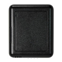
• C4-Z2IO ZigBee IO and Extender
• Four wall mounting screws
• Four plastic dry wall anchors
• Two IR emitters
• Micro USB power supply
Requirements
• Composer Pro 2.10.0 or higher
Features
The ZigBee IO and Extender (Z2IO) is a single device that
combines the features of:
• Remote relays (up to two)
• Remote contact sensors (up to four)
• Remote thermistors (two)
• Internal contact (internal magnetic reed switch)
• ZigBee (IEEE 802.15.4) extender
• ZigBee-to-IR converters
Any of these inputs can be used to trigger and control automated
events—such as sending an e-mail or turning on a cabinet light
when its door is opened—throughout the Control4 system.
With this device, you can extend home automation control to the
most remote of locations and applications inside or outside the
home, reducing the need to run control wires over long distances
(or where you can’t run any wires at all).
As ZigBee to IR
The two 3.5 mm IR ports allow you to connect up to two standard
IR emitters to control any IR-controlled devices, such as TVs,
DVRs, and receivers.
When connecting IR emitters, make note of which port each
emitter is connected to (labeled “1” and “2”).
IR codes sent from the controller to the ZigBee IO and Extender
are cached at the device, resulting in faster IR control response
times.
Micro USB IR 1 IR 2
Note: Y IR cables can be used, or IR cables can be
spliced together (in parallel, not in series), to increase
the number of controlled devices. Be aware that these
connected emitters cannot be controlled independently
but will all fire simultaneously from the shared IR
port. Test to verify that there is no crossover code
functionality between devices sharing the same IR port
to avoid unwanted side eects.
As a contact and relay
The device has an internal contact along one edge that can
be used to detect open or closed states when installed with
a mounted magnet. Up to four contacts (besides the internal
contact) or two additional relays, or a combination of the two,
can be used. Each option is outlined below in “Contact and Relay
Wiring Options,” and after it’s physically wired, the correct option
must be set on the Properties tab as outline further below in the
section “IO Options.”
As a relay
As a relay, this device provides wireless control of garage door
openers, window coverings, fireplaces, and pumps (along with
other relay control applications) inside or outside the home. It
integrates into Control4 systems as standard relays that can be
opened, closed, toggled, or pulsed.
The relay enables wireless control of any device controllable
by one or two low-voltage SPST relays or one simulated SPDT/
DPDT relay. These functions appear in a Control4 system as relay
outputs (relays) in Composer Pro.
SPST
(single pole single throw)
(single pole double throw)
SPDT
(double pole single throw)
DPST
(double pole double throw)
DPDT
ZigBee IO and Extender
Installation Guide

 Loading...