3CA/CF/CP IO&M B51181-002
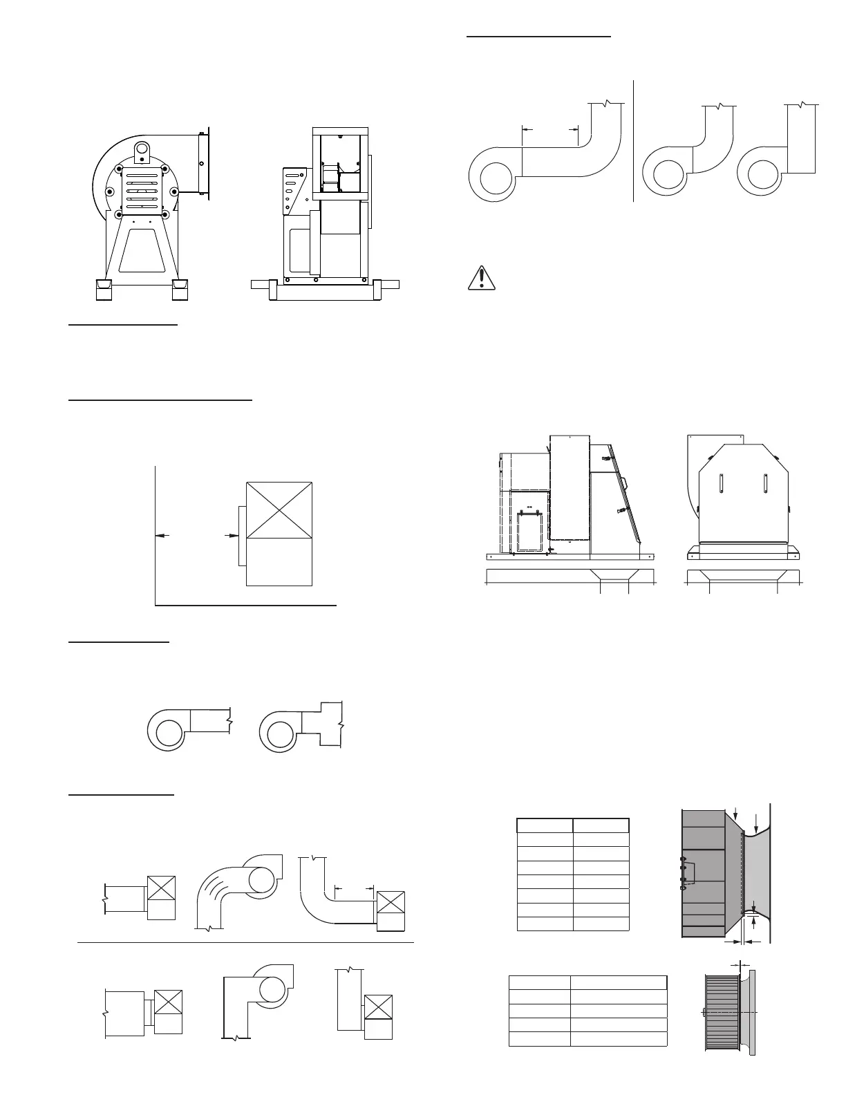
Discharge Duct Turns
Make sure that duct turns located near the fan discharge
curve in the direction of the fan’s rotation.
Discharge Duct Turns
Correct
MIN 3
DIA
CP with Optional Curb Cap and Inlet Box
NOTICE! UL 762/NFPA96 and local codes may dic-
tate additional or modications to this installation.
The installation diagram below has a solid curb cap
duct adapter placed over the top of the curb. The welded
grease duct with recommended transition is either welded
or sealed with UL recognized re caulk to both the curb
cap duct adapter and the bottom of the fan. A minimum
of two separate outlines of caulk is recommended at the
outer portion of the curb cap duct adapter.
Wheel-to-Inlet Clearance
The correct wheel-to-inlet clearance is critical to proper
fan performance. This clearance should be veried before
initial start-up since rough handling during shipment could
cause a shift in fan components. Refer to the wheel/inlet
drawing for correct overlap.
Adjust the overlap by loosening the wheel hub and mov-
ing the wheel along the shaft to obtain the correct value.
A uniform radial gap (space between the edge of the
cone and the edge of the inlet) is obtained by loosening the
inlet cone bolts and repositioning the inlet cone.
CA, CF and CP
Size Overlap
60–165 3/16”
180–245 1/4”
270–300 5/16”
330–365 3/8”
402 7/16”
445–490 1/2”
540–730 13/16”
RADIAL
CLEARANCE
INLET
CPFD, CPFB
Size Gap/Clearance
100 - 150 1/4
180 3/16
220 1/2
250 - 300 3/4
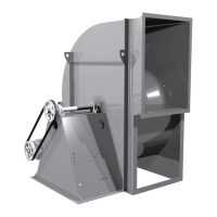
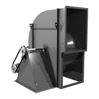
3. Position isolators under fan (or isolation base/rails)
and secure bolts.
4. Remove blocks and allow fan to rest on oor. Isolators
must be installed on a level surface (leveling should
not be required).
5. Secure isolators to mounting surface.
Duct Installation
Ecient fan performance relies on the proper installa-
tion of inlet and discharge ducts. Be sure your fan con-
forms to the guidelines below.
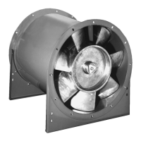
Non-Ducted Inlet Clearance
If your fan has an open inlet (no duct work), the fan must
be placed 1 fan wheel diameter away from walls and bulk-
heads. An inlet bell should be used in this case.
Non-Ducted Inlet Clearance
MIN 1 DIA
Free Discharge
Avoid a free discharge into the plenum. This will result in
lost eciency because it doesn’t allow for a static regain.
Correct
Incorrect
Free Discharge
Inlet Duct Turns
For ducted inlets, allow at least 3 fan wheel diameters
between duct turns or elbows and the fan inlet.
Incorrect
MIN 3
DIA
 Loading...