EasyManua.ls Logo

COOK CA Series - User Manual

COOK CA Series
12 pages
Print Icon
To Next Page IconTo Next Page
Loading...
1CA/CF/CP IO&M B51181-002
®
CA/CF/CP
Centrifugal Blower
INSTALLATION, OPERATION AND MAINTENANCE MANUAL
Receiving and Inspection
Carefully inspect the fan and accessories for any dam-
age and shortage immediately upon receipt of the fan.
Turn wheel by hand to ensure it turns freely and does not
bind
Inspect dampers (if supplied) for free operation of all mov-
ing parts
Record on the Delivery Receipt any visible sign of damage
Handling
Lift the fan by the base or lifting eyes.
NOTICE! Never lift by the shaft, motor or housing.
Rotating Parts & Electrical Shock Hazard:
Fans should be installed and serviced by qualied person-
nel only.
Disconnect electric power before working on unit (prior to
removal of guards or entry into access doors).
Follow proper lockout/tagout procedures to ensure the unit
cannot be energized while being installed or serviced.
A disconnect switch should be placed near the fan in order
that the power can be swiftly cut o󰀨, in case of an emer-
gency and in order that maintenance personnel are pro-
vided complete control of the power source.
Grounding is required. All eld-installed wiring must be
completed by qualied personnel. All eld installed wiring
must comply with National Electric Code (NFPA 70) and all
applicable local codes. Ensure the power supply (voltage,
frequency and current carrying capacity of wires) is in ac-
cordance with the motor nameplate.
Fans and blowers create pressure at the discharge and
vacuum at the inlet. This may cause objects to get pulled
into the unit and objects to be propelled rapidly from the
discharge. The discharge should always be directed in a
safe direction and inlets should not be left unguarded. Any
object pulled into the inlet will become a projectile capable
of causing serious injury or death.
When air is allowed to move through a non-powered fan,
the impeller can rotate, which is referred to as windmill-
ing. Windmilling will cause hazardous conditions due to
unexpected rotation of components. Impellers should be
blocked in position or air passages blocked to prevent draft
when working on fans.
Friction and power loss inside rotating components will
cause them to be a potential burn hazard. All components
should be approached with caution and/or allowed to cool
before contacting them for maintenance.
Under certain lighting conditions, rotating components
may appear stationary. Components should be veried to
be stationary in a safe manner, before they come into con-
tact with personnel, tools or clothing.
Failure to follow these instructions could result in death or
serious injury.
The attachment of roof mounted fans to the roof curb as
well as the attachment of roof curbs to the building struc-
ture must exceed the structural requirements based on the
environmental loading derived from the applicable build-
ing code for the site. The local code o󰀩cial may require
variations from the recognized code based on local data.
The licensed engineer of record will be responsible for pre-
scribing the correct attachment based on construction ma-
terials, code requirements and environmental e󰀨ects spe-
cic to the installation.
This publication contains the installation, operation and
maintenance instructions for standard units of the CA, CF,
and CP: Centrifugal Blowers.
CA/CF SWSI
CA-4 SWSI
CA DWDI
CA-4 DWDI
CPFD
CPFB
CAF-DW
CPA/CPA-A/CPS/
CPS-A/CPV
Carefully read this publication and any
supplemental documents prior to any
installation or maintenance procedure.
Loren Cook catalogs, CA/CF and CP, provide additional
information describing the equipment, fan performance,
available accessories and specication data.
For additional safety information, refer to AMCA Publi-
cation 410-96, Safety Practices for Users and Installers of
Industrial and Commercial Fans.
All of the publications listed above can be obtained from:
lorencook.com
info@lorencook.com
417-869-6474 ext. 166
For information and instructions on special equipment,
contact Loren Cook Company at 417-869-6474.
CA SWSI Shown
Question and Answer IconNeed help?

Do you have a question about the COOK CA Series and is the answer not in the manual?

Summary

Safety and General Information

Warning: Electrical and Mechanical Hazards

Critical safety warnings regarding rotating parts, electrical shock, and installation precautions.

Receiving and Inspection

Procedures for receiving and inspecting the fan upon arrival to ensure proper condition.

Handling

Guidelines for safely lifting and handling the fan unit, emphasizing care for its components.

Storage and Installation Preparation

Storage Guidelines

Instructions for storing the fan unit properly to prevent damage before installation.

Outdoor Storage Precautions

Additional measures for storing the fan unit outdoors to protect it from environmental factors.

Installation Procedures

Motor Installation

Guidance on installing the motor, especially if shipped separately from the fan.

Foundation Requirements

Requirements and guidelines for constructing a proper foundation for floor-mounted units.

Vibration Isolation

Methods for isolating the fan to prevent vibration transfer to the building structure.

Duct Installation and Clearance

Discharge Duct Turns

Proper orientation of duct turns near the fan discharge to align with fan rotation.

Non-Ducted Inlet Clearance

Specification for placing fans with open inlets away from walls and bulkheads.

Free Discharge

Caution against free discharge into plenums due to lost efficiency and static regain.

Inlet Duct Turns

Recommended spacing for duct turns or elbows from the fan inlet.

Wheel-to-Inlet Clearance

Critical clearance verification before start-up to ensure proper fan performance.

Belt and Pulley Installation

Belt and Pulley Installation

Detailed steps for installing belts and pulleys, including tension adjustment.

Pulley Alignment

Procedure for aligning pulleys using the setscrew and mounting holes.

Wiring and Motor Operation

Wiring Installation

Instructions for wiring the motor, emphasizing securing terminal bolts and removing excess wire.

Wheel Rotation

How to check and verify the correct rotation direction of the fan wheel.

Motor Wiring Diagrams

References to wiring diagrams for single-phase and three-phase motors.

Operation and Maintenance

Single Phase, Dual Voltage Wiring

Wiring connections for single-phase, dual-voltage motors.

Three Phase Wiring

Wiring configurations for three-phase, nine-lead motors.

Two Speed, Two Winding, Two Phase Motors

Wiring instructions for two-speed, two-winding, two-phase motors.

Troubleshooting

Identifies common problems like low capacity, excessive vibration, and motor issues.

Lubrication and Inspection

Variable Frequency Drives

Information on VFD compatibility and recommendations.

Grounding

Guidance on proper grounding of the fan and VFD for safety.

Fan Bearings Lubrication

Details on lubricating fan bearings based on conditions and interval recommendations.

Inspection

Schedule and requirements for inspecting the fan, including 30-minute and 24-hour checks.

Motor and Bearing Specifications

Motor Bearings

Information on motor bearing lubrication, intervals, and compatible greases.

Relubrication Intervals

Tables detailing relubrication intervals for various motor sizes and conditions.

Motor Services

Procedure for addressing defective motors within the warranty period.

Changing Shaft Speed

Instructions on adjusting fan speed using variable pitch pulleys.

Pulley and Belt Replacement

Steps for replacing pulleys and belts, including shaft preparation.

Bearing Replacement

Detailed procedure for removing and replacing fan pillow block bearings.

Troubleshooting and Parts

Troubleshooting

Identifies common problems like low capacity, excessive vibration, and motor issues.

Parts List: CA,CF SWSI Arrangements

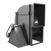
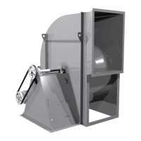
Lists and illustrates parts for CA, CF SWSI fan arrangements 1, 3, 9, and 10.

Parts List: CA, CF DWDI & CAF-DWDI

Lists and illustrates parts for CA, CF DWDI and CAF-DWDI fan models.

Parts List: CPFB, CPA, CPS, CPV

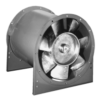
Lists and illustrates parts for CPFB, CPA, CPS, CPV fan models and accessories.

Limited Warranty

Limited Warranty

Details the terms, conditions, and duration of the product warranty.

Overview

The Loren Cook CA/CF/CP Centrifugal Blower is a robust air-moving device designed for industrial and commercial applications. This manual provides comprehensive instructions for its installation, operation, and maintenance, ensuring safe and efficient performance.

Function Description

The primary function of the CA/CF/CP Centrifugal Blower is to move air, creating pressure at the discharge and vacuum at the inlet. This makes it suitable for various ventilation, exhaust, and air handling systems. The blower is available in several configurations, including Single Width Single Inlet (SWSI), Double Width Double Inlet (DWDI), and Plug Fan Direct Drive (PFD), catering to diverse application requirements. Its design allows for efficient air movement, contributing to environmental control and air quality in industrial and commercial settings.

Usage Features

The CA/CF/CP blower is designed for versatility and ease of integration into existing systems.

  • Installation Flexibility: The manual details various arrangements for installation, including ceiling-mounted and floor-mounted options, with specific instructions for spring and rubber-in-shear isolators to mitigate vibration and noise. This adaptability allows for optimal placement within a facility.
  • Ductwork Integration: Proper installation of inlet and discharge ducts is crucial for efficient fan performance. The manual provides guidelines for non-ducted inlet clearance, free discharge, and inlet/discharge duct turns, ensuring that the blower operates at its peak efficiency when integrated into a duct system. Special considerations are given for CP models with optional curb caps and inlet boxes, particularly regarding UL 762/NFPA96 and local code compliance for grease duct applications.
  • Wheel-to-Inlet Clearance: Critical for proper fan performance, the wheel-to-inlet clearance can be adjusted by loosening the wheel hub and moving the wheel along the shaft. The manual provides specific overlap values for different fan sizes, allowing for precise calibration during installation.
  • Motor and Belt Drive System: Most motors are shipped mounted with belts and drives installed, though heavier motors may require field installation. The manual covers wiring installation, emphasizing the importance of proper slack for motor movement and adherence to wiring diagrams. For belt-driven units, instructions are provided for belt and pulley installation, including tension adjustment and alignment to prevent efficiency loss and damage. Variable pitch pulleys allow for easy adjustment of fan speed, with clear guidance on how to increase or decrease speed while adhering to RPM limits.
  • Wheel Rotation: The fan's wheel rotation is critical for performance and motor longevity. For single-phase motors, rotation is factory-set. For 3-phase motors, which are electrically reversible, the manual provides instructions for checking and correcting rotation by switching supply leads, preventing overheating and damage.
  • Variable Frequency Drives (VFDs): For units operated with VFDs, the manual highlights the importance of VFD-compatible motors, proper grounding of the fan frame, motor, and VFD, and the potential need for line reactors to reduce over-voltage spikes. It also stresses the responsibility of the installer to perform coast-down tests to identify and remove resonant frequencies from the operating range, which is crucial for extending fan life and maintaining warranty validity.

Maintenance Features

Regular maintenance is essential for the longevity and optimal performance of the CA/CF/CP Centrifugal Blower.

  • Inspection Schedule: The manual recommends initial inspections at 30-minute, 8-hour, and 24-hour intervals after satisfactory operation. A comprehensive maintenance schedule is advised, with inspection frequency depending on operating conditions. Fans exhausting corrosive or contaminated air require more frequent inspections (monthly initially, then every three months), while those handling non-contaminated air can be inspected twice yearly.
  • Key Inspection Points: Maintenance checks include inspecting bolts, setscrews, motor mounting bolts, belt alignment and tension, and variable inlet vanes for freedom of operation and wear. Worn components, such as setscrews and belts, should be replaced promptly.
  • Lubrication: Greasable fan bearings are lubricated via a grease fitting. The manual provides a detailed lubrication conditions chart based on fan class, status (normal or extreme conditions), and shaft size, specifying maximum operation hours between lubrication. Exceptions for periodic applications, higher temperatures, and vertical shafts are also noted. It emphasizes slow grease application to avoid bursting seals and recommends specific lithium-based grease (NLGI grade 2) or Mobiltemp SHC 32 for higher temperatures, warning against mixing incompatible greases.
  • Bearing Replacement: Detailed instructions are provided for replacing pillow block ball bearings, including marking component positions, removing pulleys and wheels, cleaning shafts, and properly seating new bearings. Specific steps are outlined for different fan arrangements.
  • Troubleshooting: A dedicated troubleshooting section helps identify and resolve common issues such as low capacity or pressure, excessive vibration and noise, overheated motors, and overheated bearings. This section guides users through potential causes like incorrect rotation, poor inlet conditions, improper wheel alignment, loose belts, or lubrication needs, facilitating quick diagnosis and repair.
  • Storage: For units stored prior to installation, the manual advises completely filling bearings with grease or moisture-inhibiting oil, rotating the wheel periodically, and protecting the fan from dust, debris, and weather. For outdoor storage, additional steps include coating the shaft with rust preventative, wrapping bearings, and covering inlets and outlets.

COOK CA Series Specifications

General IconGeneral
Wheel TypeForward Curved
ModelCA Series
CategoryBlower
DriveDirect drive
Power SourceElectric
Noise LevelVaries with model, contact factory
WeightVaries with model
DimensionsVaries with model
Voltage115/208-230/460