5CA/CF/CP IO&M B51181-002
Recommended Torque for Setscrews/Bolts (IN-LB)
Setscrews Hold Down Bolts
Size
Key Hex
Across
Flats
Recommended
Torque
Size
Recommended
Torque
Min. Max.
#8 5/64” 15 21 3/8”-16 324
#10 3/32” 27 33 1/2”-13 780
1/4 1/8” 70 80 5/8 ”-11 1440
5/16 5/32” 140 160 3/4”-10 2400
3/8 3/16” 250 290 7/8”-9 1920
7/16 7/32” 355 405 1”-8 2700
1/2 1/4” 560 640 1-1/8”-7 4200
5/8 5/16” 1120 1280 1-1/4”-7 6000
3/4 3/8” 1680 1920 - -
7/8 1/2” 4200 4800 - -
1 9/16” 5600 6400 - -
Operation
Pre-Start Checks
1. Lock out all the primary and secondary power sources.
2. Ensure fasteners and setscrews, particularly those used for
mounting the fan, are tightened.
3. Inspect belt tension and pulley alignment.
4. Inspect motor wiring.
5. Ensure belt touches only the pulleys.
6. Ensure fan and ductwork are clean and free of debris.
7. Inspect wheel-to-inlet clearance. The correct wheel-to-inlet
clearance is critical to proper fan performance.
8. Close and secure all access doors.
9. Restore power to fan.
Start-Up
Turn on the fan. In variable speed units, set fan to its low-
est speed and inspect for the following:
• Direction of rotation
• Excessive vibration
• Unusual noise
• Bearing noise
• Improper belt alignment or tension (listen for squealing)
• Improper motor amperage or voltage
NOTICE! If a problem is discovered, immediately shut
o the fan. Lock out all electrical power and check for
the cause of the trouble. Refer to Troubleshooting.
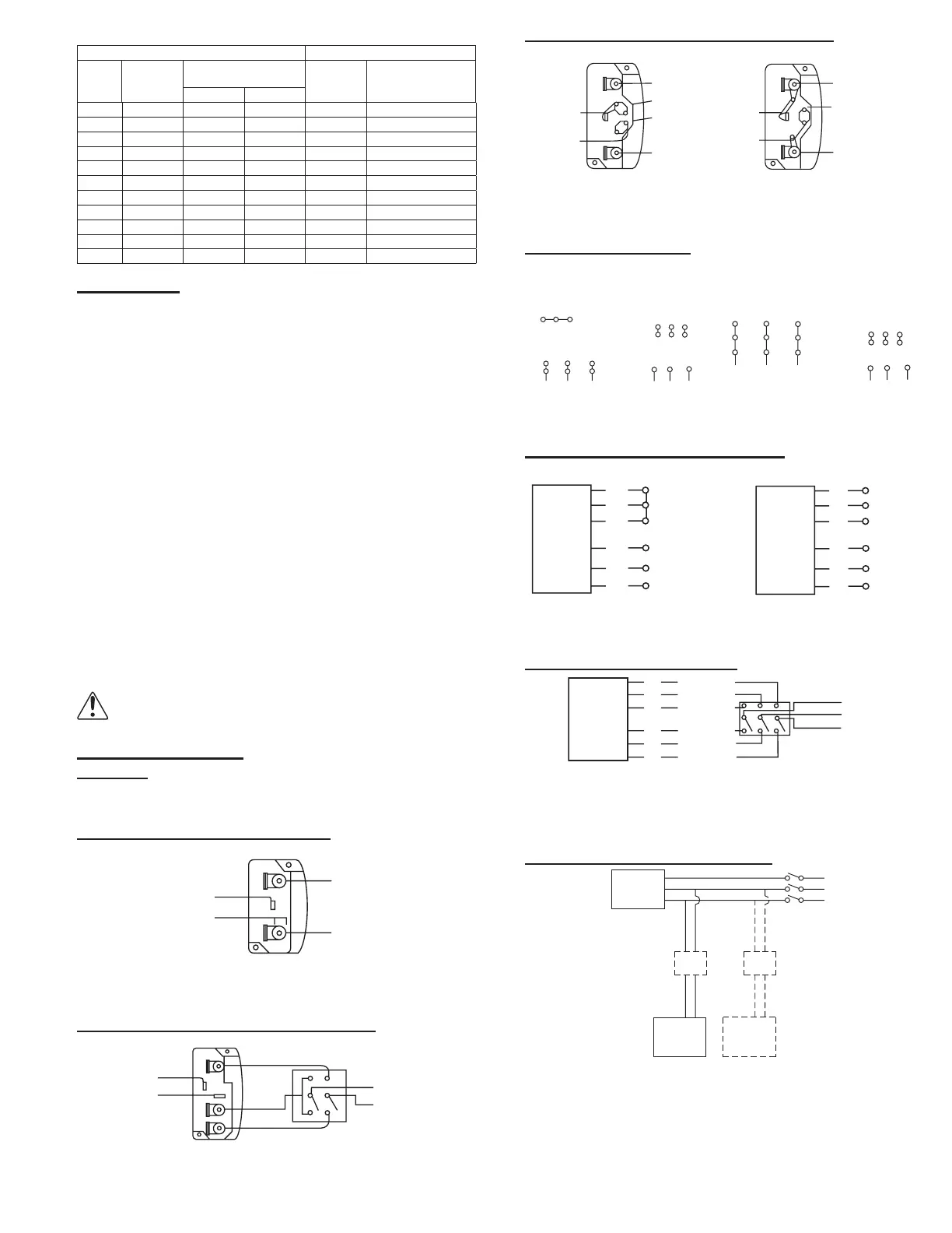
Wiring Dagrams
Vari-Flow
For EC or VF see EC Motor Wiring supplement. For VF2 see
PM wiring supplement.
Single Speed, Single Phase Motor
1
4
L
2
L
1
When ground is required, attach to ground A or B with No. 6
thread forming screw. To reverse, interchange T-1 and T-4.
2 Speed, 2 Winding, Single Phase Motor
T-1
4
Low Speed
High Speed
L
1
L
2
When ground is required, attach to ground A or B with No. 6 thread
forming screw. To reverse, interchange T-1 and T-4 leads.
Single Speed, Single Phase, Dual Voltage
T-5
Link A
Link B
Low Voltage
Line
L
2
L
1
Link A
and B
L
1
L
2
T-5
J-10
When ground is required, attach to ground A or B with No. 6
thread forming screw. To reverse, interchange T-5 and J-10 leads.
3 Phase, 9 Lead Motor
4
5
6
1
7
2
8
3
9
L
1
L
2
L
3
456
7
8
9
12
3
L
1
L
2
L
3
Low Voltage
208/230 Volts
High Voltage
460 Volts
3 Phase, 9 Lead Motor
Y-Connection
7
1
6
789
4
5
6
12
3
Low Voltage
olts
High V
460 Volts
8
2
4
9
3
5
L
1
L
3
L
L
1
L
3
L
2
3 Phase, 9 Lead Motor
Delta-Connection
To reverse, interchange any two line leads.
2 Speed, 1 Winding, 3 Phase Motor
Motor
1
2
3
4
5
6
Together
Line
L
1
L
2
L
1
2
3
4
5
6
Open
L
1
L
2
L
3
Motor
To reverse, interchange any two line leads. Motors require mag-
netic control.
2 Speed, 2 Winding, 3 Phase
L
1
T
1
T
2
T
3
Low Speed
Low Speed
Low Speed
High Speed
High Speed
High Speed
Motor
T
13
T
12
T
11
L
2
Line
L
3
To reverse:
High Speed - interchange leads T
11
and T
12
.
Low Speed - interchange leads T
1
and T
2
.
Both Speeds - interchange any two line leads.
Typical Damper Motor Schematic
Fan
Motor
Damper
Motor*
Second
Damper
ansformer**
Transformer*
L3
L2
L1
For 3-Phase, damper motor voltage should be the same be-
tween L
1
and L
2
. For single phase application, disregard L
3
.
*Damper motors may be available in 115, 230 or 460 volt mod-
els. The damper motor nameplate voltage should be veried pri-
or to connection.
**A transformer may be provided in some installations to correct
the damper motor voltage to the specied voltage.
 Loading...